Access
Free
FREE
Download via email link

Link valid for 24h • Max 3 downloads


Support my work

If this project helped you, consider supporting future free uploads 🙏


✔ Free download via email link
✔ Clear license terms

Low Cost DIY Geiger Counter with SI3BG Tube ATmega168PA and TM1638 Display

Low Cost DIY Geiger Counter with SI3BG Tube ATmega168PA and TM1638 Display

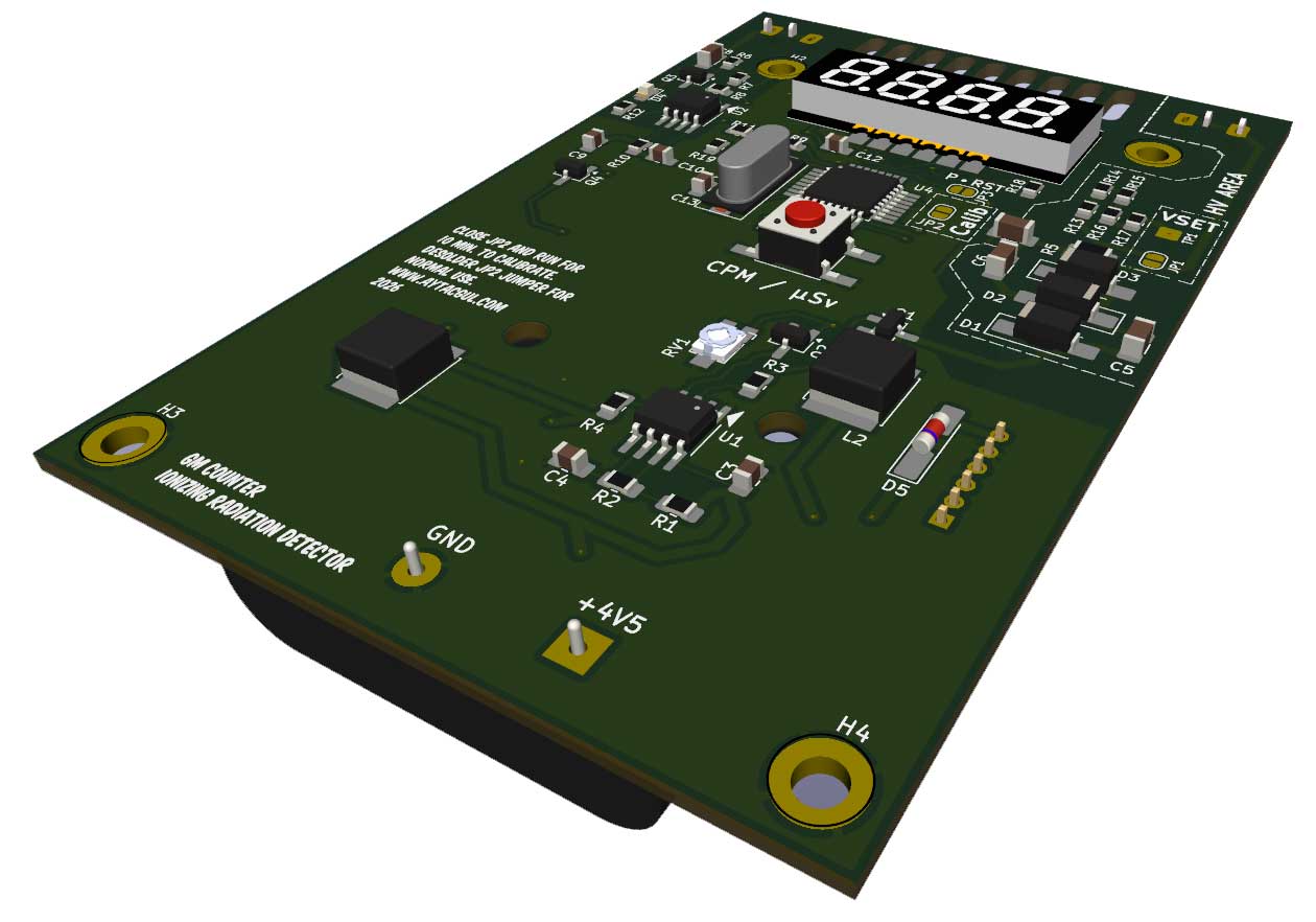
In this project, I designed and built a compact Geiger-Müller radiation detector using the SI3BG GM tube and a custom PCB. The device is powered by three AA batteries and features a 4-digit 7-segment LED display driven by a TM1638 controller.

The high voltage for the GM tube is generated using a RadiationD-V1.1 style boost and multiplier circuit based on the NE555 timer and MMBTA42 transistor. The output voltage is adjustable and calibrated to operate the SI3BG tube in its optimal plateau region (~400–450V).

The microcontroller is an ATmega168PA (TQFP-32), fully compatible with ATmega328P. Pulse counting is handled using the INT0 external interrupt to ensure accurate event detection even during sleep mode.

The device supports:

  • CPM (Counts Per Minute) display
  • µSv/h display with automatic decimal formatting
  • 10-minute background calibration mode (via jumper)
  • EEPROM storage of calibration values
  • Automatic sleep after 5 minutes of inactivity
  • Wake-up via push button
  • Support for both Common Cathode and Common Anode 7-segment displays

All PCB files (Gerbers, KiCad project, schematics) and source code are provided.

This design aims to be:

  • Compact
  • Low power
  • Electrically safe (proper creepage in HV area)
  • Flexible for different display types
Display Mode Selection PCB according to CA

#define DISPLAY_COMMON_ANODE 1   // 1 = Common Anode (SEG/GRID swapped)
                                 // 0 = Common Cathode (standard)


SOURCE CODE

/*
===========================================================
 DIY Geiger Counter – SI3BG + ATmega168PA + TM1638
===========================================================

Features:
- Counts Geiger pulses via INT0 (PD2)
- Displays CPM or µSv/h
- 10 minute calibration mode (JP2 closed at boot)
- Stores background CPM in EEPROM
- Auto sleep after 5 minutes
- Wake on button press
- Supports Common Cathode AND Common Anode 7-segment displays

Display type selection:
  DISPLAY_COMMON_ANODE = 0 → Common Cathode
  DISPLAY_COMMON_ANODE = 1 → Common Anode (SEG/GRID swapped)

Author: [Your Name]
===========================================================
*/

#define DISPLAY_COMMON_ANODE 1

#include 
#include 
#include 
#include 

// ---------------- PIN DEFINITIONS ----------------
#define PIN_PULSE 2     // PD2 / INT0
#define PIN_BUTTON 3    // PD3 / INT1
#define PIN_STB 4       // TM1638 STB
#define PIN_CLK 5       // TM1638 CLK
#define PIN_DIO 6       // TM1638 DIO
#define PIN_CAL A0      // Calibration jumper

// ---------------- CONSTANTS ----------------
#define CAL_TIME_SECONDS 600
#define SLEEP_TIMEOUT 300
#define CPM_WINDOW 10

// µSv conversion factor (0.005 µSv/h per CPM default)
#define K_X1000 5

// ---------------- GLOBAL VARIABLES ----------------
volatile uint16_t pulses_1s = 0;
volatile bool wdt_flag = false;
volatile bool button_flag = false;

uint32_t seconds = 0;
uint32_t cpm = 0;
uint16_t bg_cpm = 0;

enum Mode { MODE_CPM, MODE_USV };
Mode displayMode = MODE_CPM;

// ---------------- INTERRUPTS ----------------
void pulseISR() { pulses_1s++; }
void buttonISR() { button_flag = true; }
ISR(WDT_vect) { wdt_flag = true; }

// ---------------- WDT SETUP ----------------
void setupWDT() {
  cli();
  MCUSR &= ~(1<>=1;
  }
}

void tmCommand(uint8_t cmd){
  digitalWrite(PIN_STB,LOW);
  tmWrite(cmd);
  digitalWrite(PIN_STB,HIGH);
}

// ---------------- DISPLAY DRIVER ----------------
const uint8_t digits[10]={
0x3F,0x06,0x5B,0x4F,0x66,
0x6D,0x7D,0x07,0x7F,0x6F};

void display4(uint8_t seg[4]){
#if DISPLAY_COMMON_ANODE
  uint8_t grid[8]={0};
  for(int s=0;s<8;s++){
    for(int d=0;d<4;d++){
      if(seg[d]&(1<9999){ for(int i=0;i<4;i++) out[i]=0x40; }
  else{
    for(int i=3;i>=0;i--){
      out[i]=digits[value%10];
      value/=10;
    }
  }
  display4(out);
}

void showUSV(uint32_t cpm){
  uint32_t usv_x100 = (cpm>K_X1000)? (cpm*K_X1000)/10 : 0;
  uint8_t out[4]={0};
  uint16_t v=usv_x100;
  out[3]=digits[v%10]; v/=10;
  out[2]=digits[v%10]|0x80; v/=10;
  out[1]=digits[v%10]; v/=10;
  out[0]=digits[v%10];
  display4(out);
}

// ---------------- CALIBRATION ----------------
void calibration(){
  uint32_t total=0;
  for(int i=0;i=CPM_WINDOW){
      cpm=sum*6;
      sum=0;
      window=0;
    }
  }

  if(button_flag){
    button_flag=false;
    displayMode = (displayMode==MODE_CPM)?MODE_USV:MODE_CPM;
  }

  if(displayMode==MODE_CPM) showCPM(cpm);
  else showUSV(cpm);
}


1. Interrupts
  • pulseISR() counts every Geiger pulse.

  • buttonISR() handles toggle and wake.

  • WDT_vect creates a precise 1-second time base.

2. Watchdog Timer

Configured in interrupt mode (~1 second).
Used for:

  • CPM calculation window

  • Calibration timing

  • Sleep timing

3. Display Driver

Two modes:

  • Common Cathode: direct segment write.

  • Common Anode: converts digit segment data into segment-wise digit masks (SEG/GRID swap logic).

This allows a single firmware for both display types.

4. CPM Calculation
  • Counts pulses in 10-second window.

  • Multiplies by 6 to compute CPM.

5. µSv/h Calculation

Uses fixed-point math:

µSv/h ×100 = CPM × K / 10
No floating-point used → lower flash usage.

6. Calibration Mode

If jumper is closed at boot:

  • Measures for 10 minutes

  • Calculates background CPM

  • Stores in EEPROM

No firmware re-upload required.

7. Sleep Mode

After 5 minutes inactivity:

  • Display off

  • MCU power-down

  • Wake on button interrupt