
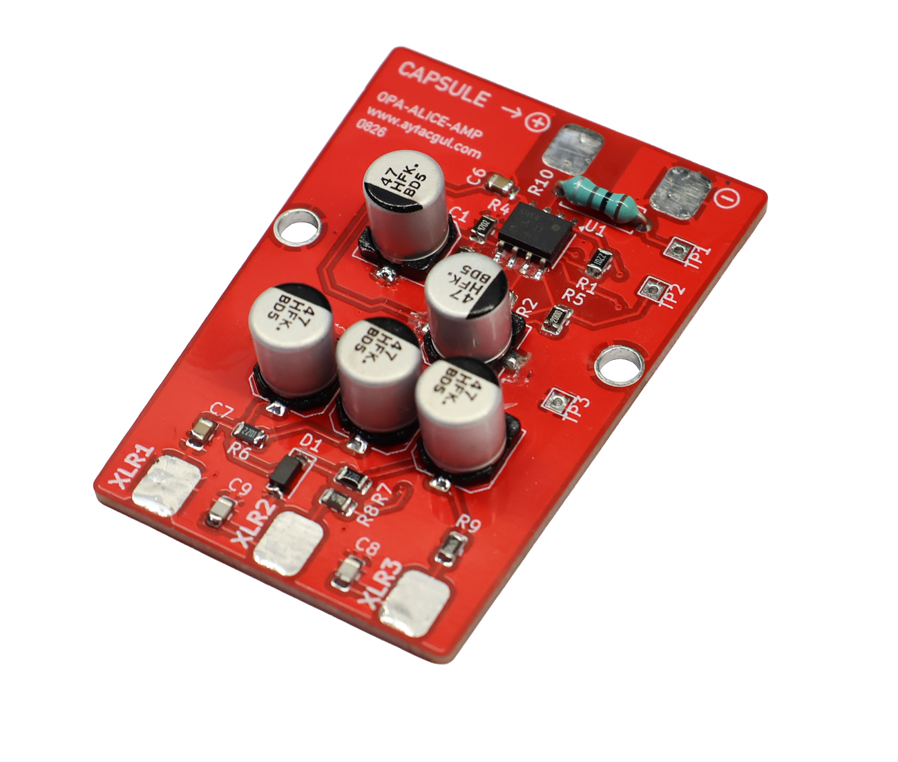
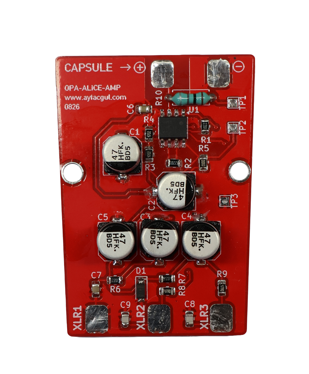
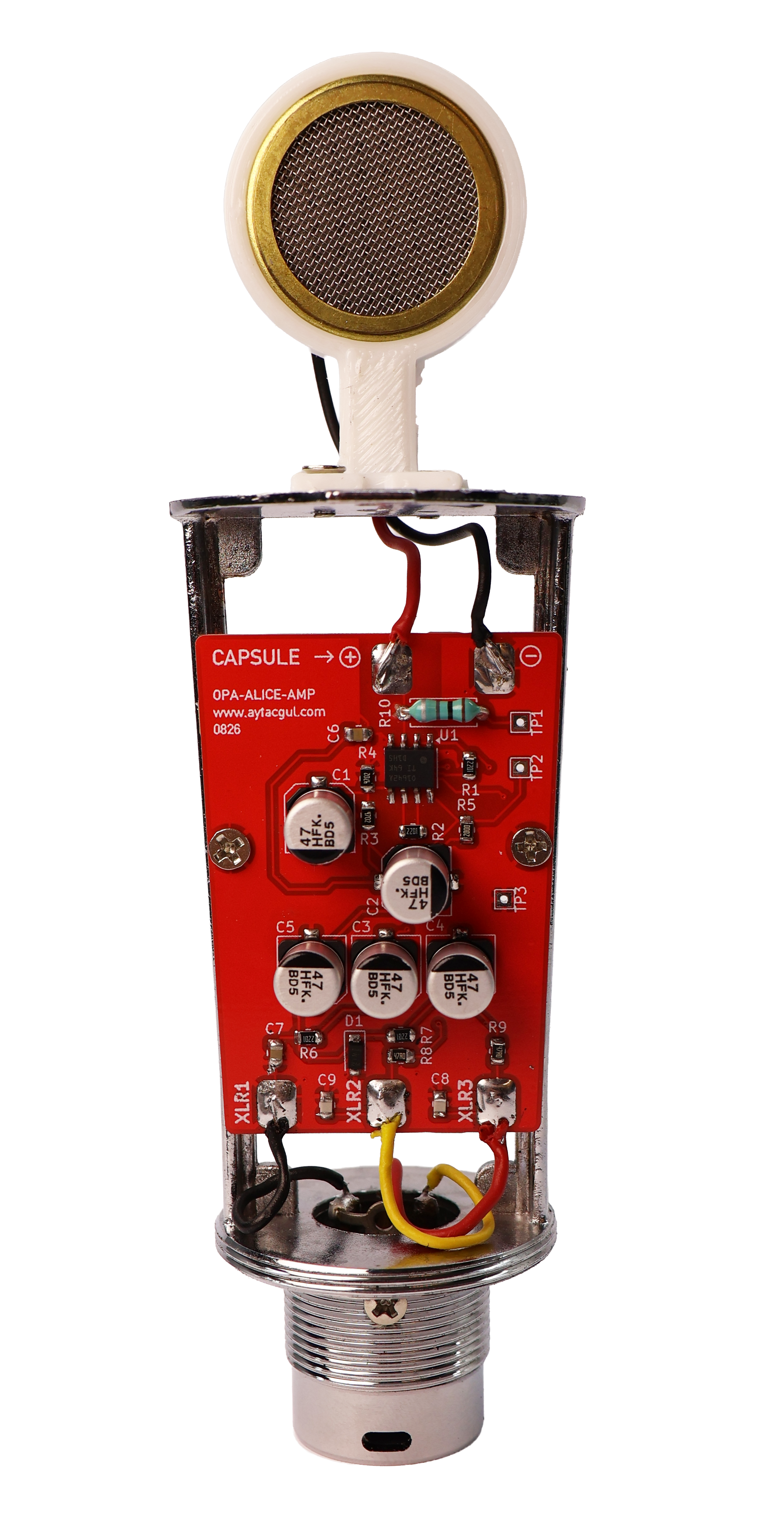
This project is a compact phantom-powered balanced microphone driver built around the Texas Instruments OPA1642 dual JFET-input audio operational amplifier.
The circuit was designed as an operational-amplifier implementation of the well-known Alice-style microphone topology. The microphone signal is buffered with one half of the OPA1642, while the second amplifier generates an inverted copy of the same signal. These two signals are then AC-coupled to the XLR output, producing a balanced differential audio signal suitable for conventional microphone preamplifiers and audio interfaces.
An important feature of the design is that no separate DC power connector is required. The complete circuit obtains its operating power from the standard 48 V phantom supply available on the XLR connection. The phantom voltage is reduced and regulated locally before being used by the OPA1642.
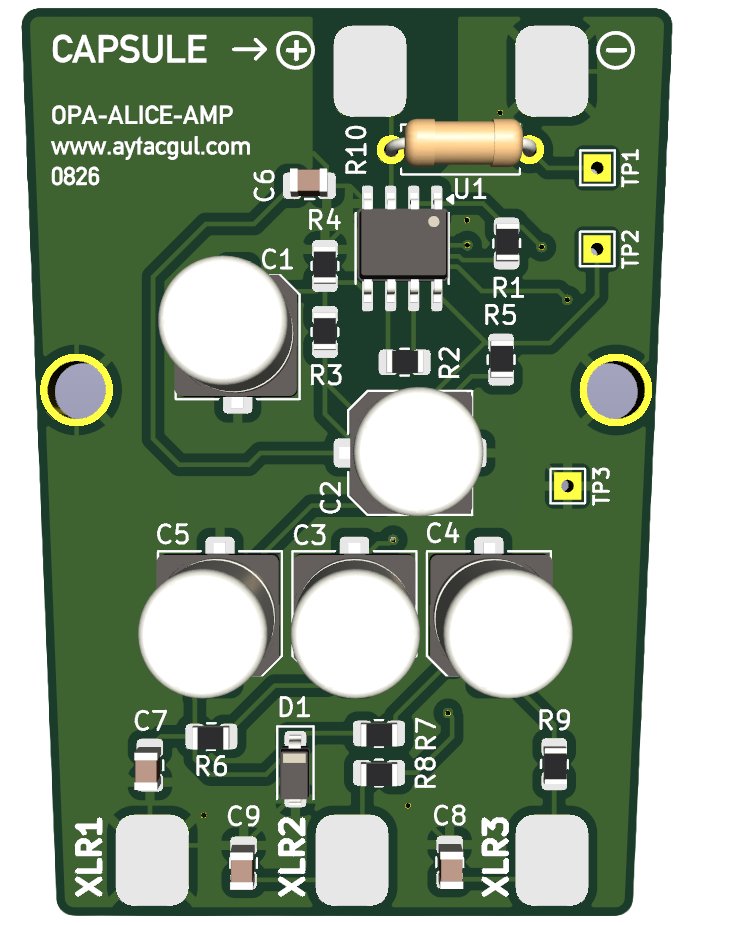
The PCB contains the OPA1642, phantom-power supply section, virtual reference generator, balanced output circuitry, RF filtering, microphone connection and XLR solder pads on a single compact board.
Circuit Overview
The complete signal path can be divided into five functional sections:
- Microphone input and high-impedance biasing
- OPA1642 input buffer
- Unity-gain phase inverter
- Balanced XLR output stage
- Phantom-power extraction and local power regulation
The basic audio signal flow is:
Microphone Capsule
       |
       v
   OPA1642A
 Voltage Buffer
       |
       +---------------------+
       |                     |
       |                     v
       |                 OPA1642B
       |                Phase Inverter
       |                     |
       v                     v
   Direct Signal         Inverted Signal
       |                     |
      C3                    C4
       |                     |
      R8                    R9
       |                     |
   XLR Pin 2             XLR Pin 3

XLR Pin 1 = Ground / Shield
The result is a true differential signal where the two XLR signal conductors carry equal but opposite audio waveforms.
OPA1642 Audio Operational Amplifier
The heart of the circuit is the OPA1642. It contains two independent high-performance JFET-input operational amplifiers in a single SOIC-8 package.
The JFET input stage is particularly useful in microphone circuits where very high input impedance is desirable. According to Texas Instruments, the OPA1642 is specifically intended for high-performance audio applications and combines low noise, very low distortion and extremely low input bias current.
| Parameter | OPA1642 Typical Value |
|---|---|
| Architecture | JFET Input |
| Number of Amplifiers | 2 |
| Voltage Noise | 5.1 nV/√Hz @ 1 kHz |
| THD+N | 0.00005% @ 1 kHz |
| Gain Bandwidth | 11 MHz |
| Slew Rate | 20 V/µs |
| Quiescent Current | 1.8 mA per channel |
| Total Supply Range | 5 V to 36 V |
| Output | Rail-to-Rail |
These characteristics make the device well suited to a microphone front end where input impedance, noise and linearity are important.
Microphone Input
The microphone element connects directly to the non-inverting input of the first OPA1642 amplifier.
In this design the input is intentionally kept at extremely high impedance. A 1 GΩ resistor, R10, connects the microphone signal node to the circuit reference voltage.
                R10
VREF --------- 1 GΩ ---------+
                              |
                              +------ OPA1642A Pin 3 (+)
                              |
                         Microphone
                              |
                             GND
The 1 GΩ resistor establishes the DC operating point while presenting an extremely small load to the microphone element.
This is significantly different from the relatively low-value bias resistors commonly found around conventional electret microphone modules. The very large resistance is intended to preserve the high-impedance characteristics of the microphone input.
First Amplifier – Input Buffer
The first half of the OPA1642, U1A, is configured as a voltage follower.
Its output is connected directly to its inverting input, producing a closed-loop gain of approximately one.
                +----------------+
Microphone ---->| +          OUT |------ Audio A
                |    OPA1642A    |
             +--| -              |
             |  +----------------+
             |          |
             +----------+
The voltage follower does not provide significant voltage gain. Its purpose is instead to buffer the extremely high-impedance microphone source and produce a low-impedance signal capable of driving the following circuitry.
Therefore:
Voltage Gain:

Av ≈ 1

VOUT ≈ VIN
Second Amplifier – Phase Inverter
The second half of the OPA1642 generates the opposite phase required for the balanced XLR output.
The buffered signal from U1A is applied to the inverting input of U1B through R1 = 2.2 kΩ. Feedback from the U1B output is provided through R2 = 2.2 kΩ.
Because R1 and R2 have the same value, the AC gain of this stage is approximately -1.
                     R1
Audio A ----------- 2.2k --------+
                                 |
                                 +------ U1B (-)
                                 |
                    R2           |
Audio B ----------- 2.2k --------+

U1B (+) = VREF
For an inverting amplifier:
Av = -R2 / R1

R1 = 2.2 kΩ
R2 = 2.2 kΩ

Av = -2200 / 2200

Av = -1
Consequently, U1B produces approximately the same signal amplitude as U1A but with opposite polarity.
Audio A = +Vsignal

Audio B = -Vsignal
This pair of signals forms the basis of the balanced microphone output.
Why Use a Balanced Output?
Professional microphone systems normally use balanced transmission because microphone signals are relatively small and can easily pick up interference over long cables.
Instead of transmitting the audio signal on a single wire referenced to ground, a balanced interface uses two conductors carrying opposite versions of the same signal.
XLR Pin 2 :  +Audio

XLR Pin 3 :  -Audio

XLR Pin 1 :  Ground / Shield
Interference picked up equally by both signal conductors appears as common-mode noise. A differential microphone preamplifier responds primarily to the difference between pins 2 and 3 and therefore rejects a substantial portion of this common-mode interference.
At the microphone:

Pin 2 = +Signal
Pin 3 = -Signal


Noise introduced in cable:

Pin 2 = +Signal + Noise
Pin 3 = -Signal + Noise


Differential receiver:

(+Signal + Noise) - (-Signal + Noise)

= +Signal + Noise + Signal - Noise

= 2 × Signal
This is one of the main reasons balanced connections are standard for professional microphones.
Output Coupling Capacitors
The direct and inverted op-amp outputs contain a DC operating voltage because the amplifier operates from a single supply around the internally generated VREF level.
This DC component must not be sent directly to the XLR audio outputs.
Two 47 µF / 50 V electrolytic capacitors, C3 and C4, provide AC coupling between the operational amplifiers and the output network.
OPA1642A OUT ---- C3 47µF ---- XLR Output A

OPA1642B OUT ---- C4 47µF ---- XLR Output B
The capacitors block the internal DC bias while allowing the microphone audio signal to pass.
47 Ω Output Resistors
Each balanced output conductor includes a 47 Ω series resistor.
R8 is connected to one XLR signal output and R9 to the other.
Audio A ---- 47Ω ---- XLR Pin 2

Audio B ---- 47Ω ---- XLR Pin 3
These resistors provide output isolation, help protect the operational amplifier from capacitive cable loading and improve stability when driving a real microphone cable.
Using the same resistance in both signal paths also helps maintain balanced output impedance.
RF Filtering
The XLR outputs include two 220 pF capacitors, C8 and C9, connected from the signal lines to ground.
Their purpose is to provide a low-impedance path for very-high-frequency interference while having negligible effect throughout the normal audio band.
                    C9
XLR Pin 2 -------- 220pF ------- GND


                    C8
XLR Pin 3 -------- 220pF ------- GND
This can help reduce RF interference entering the circuit through the microphone cable.
Phantom Power
The circuit receives its operating power from the same XLR cable that carries the audio signal.
With standard phantom powering, DC voltage is applied equally to XLR pins 2 and 3 through matched resistances at the microphone preamplifier. Because approximately the same DC potential exists on both signal conductors, the phantom supply does not normally appear as a differential audio signal.
On this board, power is extracted symmetrically from both XLR signal lines.
                XLR Pin 2
                    |
                    |
                  Output
                    |
                  2.2k
                   R6
                    |
                    +---------- Phantom DC Rail
                    |
                  2.2k
                   R7
                    |
                  Output
                    |
                XLR Pin 3
R6 and R7 are both 2.2 kΩ, maintaining symmetry between the two signal conductors.
12 V Zener Regulation
The extracted phantom voltage is substantially higher than the voltage required by the audio circuitry.
A BZT52-C12 12 V Zener diode, D1, is therefore used to clamp the internal supply rail to approximately 12 V.
XLR Phantom Power
        |
     R6 / R7
        |
        +---------+
        |         |
       D1        C5
   BZT52-C12    47µF
      12 V       |
        |         |
       GND       GND
A 47 µF capacitor, C5, together with 0.1 µF C7, provides filtering and decoupling on this regulated phantom-derived supply.
OPA1642 Supply Filtering
The OPA1642 supply is additionally isolated from the main 12 V Zener rail through R5 = 200 Ω.
After R5, another local filter consisting of C2 = 47 µF and C6 = 0.1 µF provides a clean supply for the operational amplifier.
Phantom Supply
      |
   R6 + R7
      |
  12 V Zener Rail
      |
    R5 200Ω
      |
      +---------- OPA1642 V+
      |
   +--+--+
   |     |
 C2 47µF C6 100nF
   |     |
  GND   GND
The combination of series resistance, electrolytic capacitance and ceramic bypass capacitance reduces power-supply noise reaching the sensitive audio circuitry.
Virtual Reference – VREF
Because the OPA1642 operates from a single positive supply rather than a conventional ± supply, the audio circuit requires an internal midpoint reference.
This reference is generated by two equal-value 47 kΩ resistors, R3 and R4.
OPA Supply
    |
  R3 47k
    |
    +------ VREF
    |
  R4 47k
    |
   GND
Because the two resistors are equal:
VREF = VSUPPLY × R4 / (R3 + R4)

R3 = R4 = 47 kΩ

VREF ≈ VSUPPLY / 2
With an internal supply of approximately 12 V:
VREF ≈ 12 V / 2

VREF ≈ 6 V
The actual operating voltage depends on the phantom source, current consumption and Zener operating conditions.
C1, a 47 µF capacitor, filters the VREF node and provides a low-noise AC reference for the audio stages.
Single-Supply Audio Operation
The microphone produces an alternating signal containing positive and negative excursions, while the operational amplifier has only a positive supply and ground available.
VREF effectively creates an artificial zero point near the middle of the available supply.
Real supply:

12 V  -------------------------
             Positive Headroom

6 V   -------- VREF -----------
             Audio "Zero"

0 V   -------- GND ------------
The internal audio waveform therefore moves above and below VREF instead of above and below physical ground.
C3 and C4 subsequently remove this DC offset before the audio reaches the XLR output.
Component List
| Reference | Value | Function |
|---|---|---|
| U1 | OPA1642 | Dual JFET-input audio operational amplifier |
| R1, R2 | 2.2 kΩ | Unity-gain phase inverter |
| R3, R4 | 47 kΩ | VREF divider |
| R5 | 200 Ω | Supply filtering / isolation |
| R6, R7 | 2.2 kΩ | Phantom-power extraction |
| R8, R9 | 47 Ω | Balanced output isolation |
| R10 | 1 GΩ | High-impedance microphone input bias |
| C1–C5 | 47 µF / 50 V | Bias, coupling and supply filtering |
| C6, C7 | 0.1 µF | High-frequency supply decoupling |
| C8, C9 | 220 pF | RF suppression |
| D1 | BZT52-C12 | 12 V internal supply clamp |
| J1 | XLR3 | Balanced audio and phantom-power connection |
| MK1 | Microphone | Microphone capsule connection |
| TP1 | Test Point | VREF measurement |
| TP2 | Test Point | OPA1642 supply measurement |
| TP3 | Test Point | Ground reference |
Test Points
Three test points are provided on the PCB to simplify initial testing and troubleshooting.
TP1 = VREF

TP2 = OPA1642 Supply

TP3 = Ground
Before connecting a microphone capsule, the supply and reference voltages can be checked with a multimeter.
With phantom power enabled, TP2 should show the locally generated supply for the OPA1642 and TP1 should be approximately half of that voltage.
XLR Connection
The three XLR connections are used in the conventional balanced microphone arrangement:
XLR Pin 1 = Ground / Shield

XLR Pin 2 = Balanced Audio +

XLR Pin 3 = Balanced Audio -
Both pins 2 and 3 also carry the phantom-power DC component supplied by the microphone preamplifier or audio interface.
Phantom Power and Audio on the Same Cable
At first glance it may seem unusual that the same conductors can simultaneously carry a microphone signal and a relatively high DC phantom voltage.
The principle works because phantom voltage is applied approximately equally to both balanced signal wires.
DC condition:

XLR Pin 2 = +48 V phantom component
XLR Pin 3 = +48 V phantom component

Difference ≈ 0 V


Audio condition:

XLR Pin 2 = +Audio
XLR Pin 3 = -Audio

Difference = 2 × Audio
The receiving microphone preamplifier responds to the differential audio component while the common-mode DC component provides operating power for the microphone electronics.
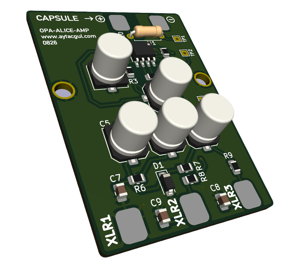
PCB Design
The PCB was designed in KiCad 8. Particular attention was given to keeping the high-impedance microphone input away from the output and phantom-power circuitry.
This is especially important around the microphone input and the 1 GΩ bias resistor because extremely high-impedance nodes are more susceptible to PCB contamination, leakage currents, humidity and external electrical interference.
The OPA1642 and associated feedback resistors are located close together to minimize trace length in the sensitive audio feedback paths.
The phantom supply filtering capacitors and the 100 nF bypass capacitors are positioned close to their associated circuit nodes to reduce supply impedance at higher frequencies.
High-Impedance PCB Considerations
The 1 GΩ input resistor makes PCB cleanliness particularly important.
Flux residue, moisture, fingerprints and contamination can create leakage paths whose resistance becomes significant when compared with a 1 GΩ bias resistor.
After soldering, the region around the microphone input, R10 and the OPA1642 non-inverting input should therefore be cleaned carefully.
For best performance:
- Keep the microphone input trace as short as practical.
- Keep phantom-power traces away from the microphone input node.
- Clean solder flux residue thoroughly.
- Avoid touching the high-impedance area after cleaning.
- Use a clean and dry PCB.
- Use proper shielding inside the microphone body.
Initial Power-Up
Before installing the microphone capsule, the power section can be checked independently.
1. Connect the board to an XLR microphone input.

2. Enable 48 V phantom power.

3. Measure between TP3 and TP2.

   TP3 = Ground
   TP2 = OPA1642 supply

4. Measure between TP3 and TP1.

   TP1 = VREF

5. VREF should be approximately half of the OPA1642 supply voltage.

6. Disable phantom power before connecting or modifying the microphone capsule.
The exact supply voltage can vary because it depends on the phantom-power source, cable resistance, circuit current and Zener operating point.
Signal Testing
An oscilloscope can also be used to verify operation.
The first and second amplifier outputs should contain signals with approximately the same amplitude but opposite polarity.
U1A Output:

       /\
      /  \
-----/    \-----
    /      \


U1B Output:

    \      /
-----\    /-----
      \  /
       \/
Viewed simultaneously on a dual-channel oscilloscope, one waveform should therefore appear inverted relative to the other.
Why Not Simply Use a Single-Ended Output?
A single-ended microphone driver would require only one amplifier output, but balanced transmission offers several advantages for microphone applications:
- Improved rejection of interference picked up by the cable
- Compatibility with standard professional microphone inputs
- Better performance with long microphone cables
- Symmetrical phantom-power extraction
- Reduced sensitivity to ground-related interference
For these reasons the additional inverter stage is useful even though it does not provide additional voltage gain.
Possible Applications
- DIY condenser microphone projects
- Studio microphone experiments
- Measurement microphone development
- High-impedance microphone capsule testing
- Balanced microphone output stages
- Phantom-powered audio projects
- DIY recording equipment
- Audio electronics experiments
Important Notes About Phantom Power
Although commonly called a 48 V supply, phantom power is current limited by series resistance in the microphone preamplifier. The microphone circuit therefore cannot treat the XLR connection as an unrestricted 48 V DC power supply.
Available voltage decreases as current consumption increases.
The complete power system must consequently be designed around both the phantom voltage and its available current.
The OPA1642 is well suited to this type of application because its quiescent current is relatively low for a high-performance audio operational amplifier.
Design Summary
Microphone Input:
    High-impedance input
    1 GΩ bias resistor

Input Amplifier:
    OPA1642A
    Voltage follower
    Gain ≈ +1

Balanced Inverter:
    OPA1642B
    R1 = 2.2 kΩ
    R2 = 2.2 kΩ
    Gain ≈ -1

Output Coupling:
    C3 = 47 µF
    C4 = 47 µF

Output Resistance:
    R8 = 47 Ω
    R9 = 47 Ω

RF Filtering:
    C8 = 220 pF
    C9 = 220 pF

Phantom Extraction:
    R6 = 2.2 kΩ
    R7 = 2.2 kΩ

Supply Regulation:
    D1 = BZT52-C12
    Zener Voltage ≈ 12 V

Supply Isolation:
    R5 = 200 Ω

Virtual Reference:
    R3 = 47 kΩ
    R4 = 47 kΩ
    VREF ≈ VSUPPLY / 2

Main IC:
    OPA1642
    Dual JFET-input audio op amp
Microphone Capsule VOXIDA CM-012 Datasheet
https://tr.aliexpress.com/item/1005006546173624.html
The finished OPA Alice microphone board combines a high-impedance microphone front end, dual JFET-input audio operational amplifier, active balanced output and phantom-power supply circuitry on a compact PCB.
The first half of the OPA1642 buffers the microphone capsule without significantly loading it. The second half generates an equal-amplitude inverted signal, allowing the circuit to drive a conventional balanced XLR microphone input.
At the same time, power for the complete circuit is extracted from the XLR phantom supply, regulated to approximately 12 V and heavily filtered before reaching the sensitive audio electronics.
The result is a relatively simple microphone driver that requires only the microphone capsule and a standard three-wire XLR connection to operate.