
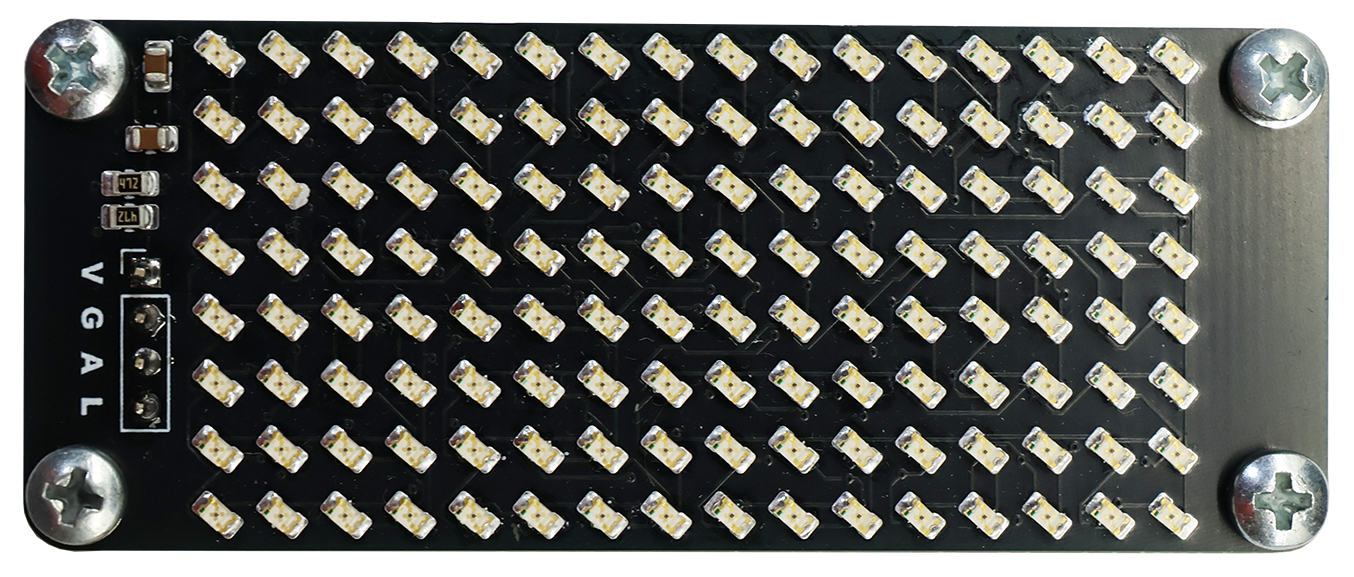
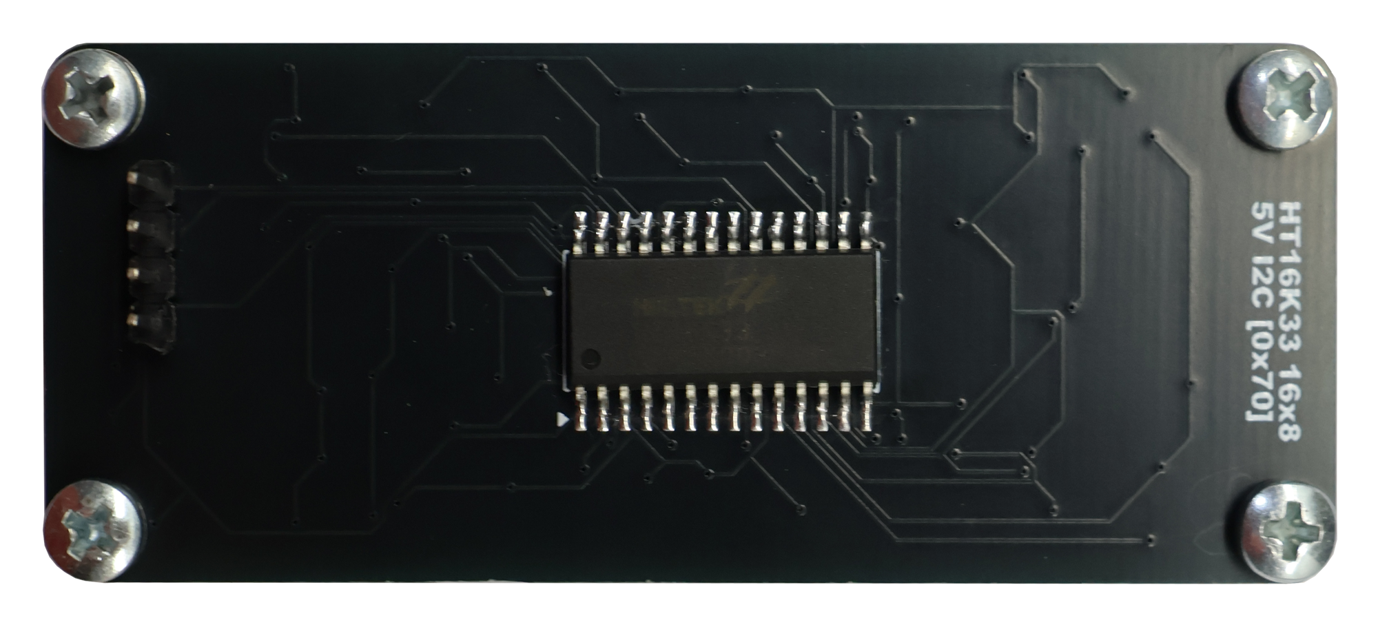
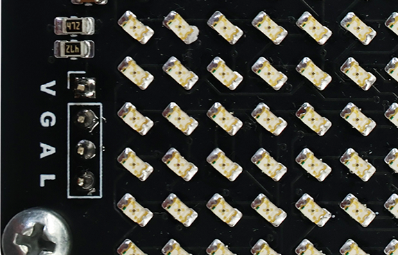
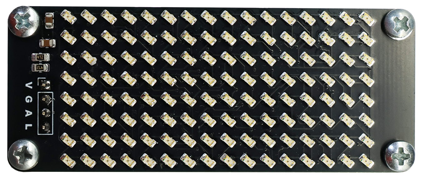
This project is a compact 16×8 dot matrix LED display board built around the Holtek HT16K33 LED controller. The display contains 128 individual 0805 SMD LEDs arranged as a matrix and can be controlled through an I2C interface using only two signal lines.
I designed this board mainly as a reusable display module for ESP32, ESP8266 and other microcontroller-based IoT projects. Instead of using a ready-made LED matrix module, all 128 LEDs are placed directly on the PCB together with the HT16K33 driver, I2C pull-up resistors and local decoupling capacitors.
The result is a thin, simple and general-purpose dot matrix display that can be used for scrolling text, numbers, icons, status information, sensor values, animations, clocks, counters and small graphical interfaces.
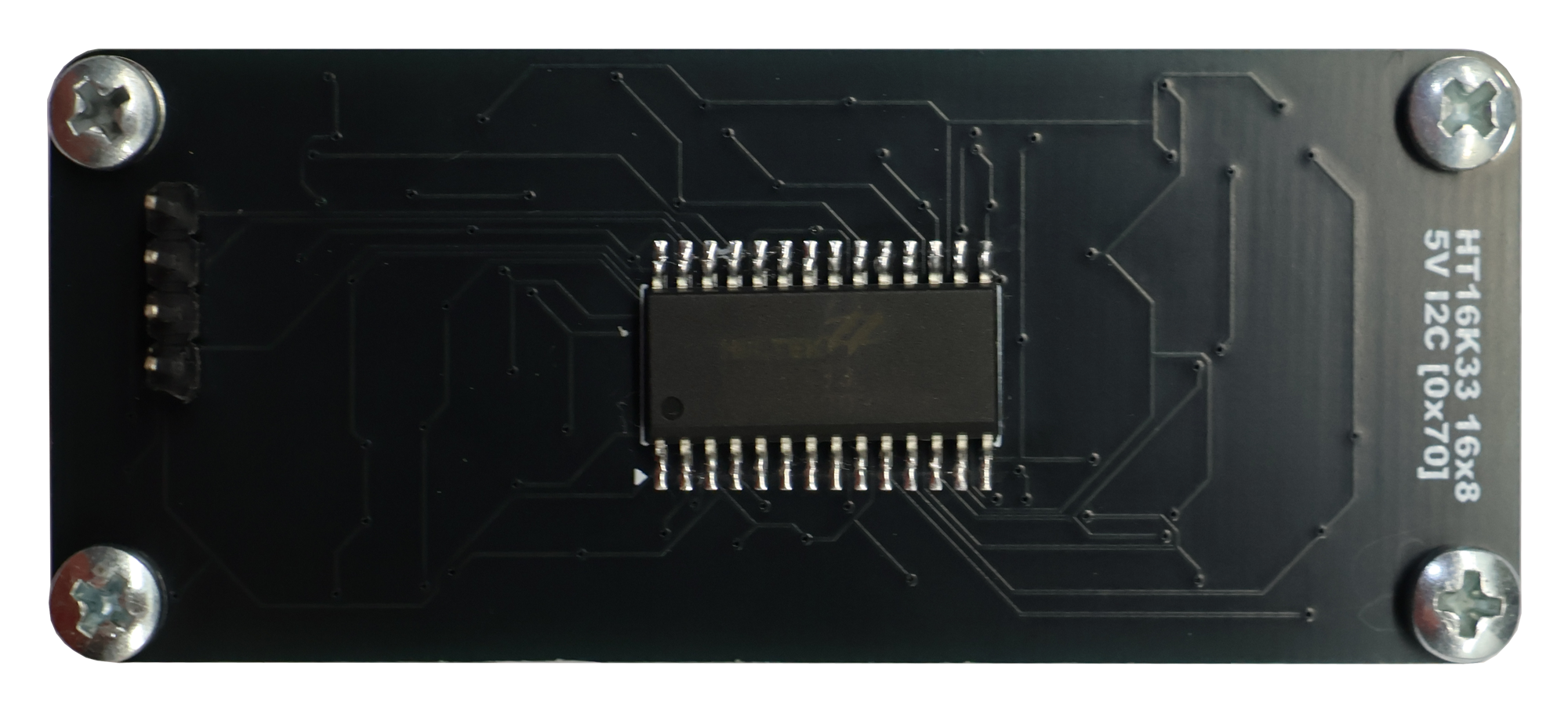
Main Features
- 16 × 8 LED matrix
- 128 individually addressable LED positions
- 128 × 0805 SMD LEDs
- HT16K33 LED matrix controller
- I2C communication
- Default I2C address:
0x70 - Only SDA and SCL required from the microcontroller
- 16-step hardware brightness control
- 16-byte display RAM
- Hardware LED multiplexing handled by the HT16K33
- Compatible with ESP32 through an appropriate I2C level interface
- Compatible with ESP8266 through an appropriate I2C level interface
- Can also be used with Arduino and other I2C capable microcontrollers
- Portrait 8×16 and landscape 16×8 software orientations
- Four mounting holes
- Compact two-layer PCB
- Approximately 74.93 × 30.48 mm PCB outline
- Rounded PCB corners
- 4-pin power and I2C connector
Why I Built This Display
Small LED matrix displays are useful in many projects, but most inexpensive modules are designed around fixed commercial matrix packages. For some applications I wanted more control over the mechanical layout, LED type, spacing and PCB dimensions.
Using individual 0805 LEDs makes it possible to define the complete matrix directly in the PCB layout. It also makes the design easier to adapt for custom enclosures, front panels, clocks or embedded IoT devices.
The HT16K33 is particularly useful for this type of project because the microcontroller does not have to perform the LED multiplexing itself. The ESP32 or ESP8266 only updates the display memory through I2C and the HT16K33 continuously refreshes the matrix in hardware.
Hardware Overview
| Component | Function |
|---|---|
| HT16K33 | LED matrix driver, display RAM and multiplexing controller |
| 128 × 0805 LED | 16×8 visible dot matrix |
| R1 4.7 kΩ | I2C pull-up resistor |
| R2 4.7 kΩ | I2C pull-up resistor |
| C1 1 µF | Local power supply filtering |
| C2 0.1 µF | HT16K33 supply decoupling |
| J1 | Power and I2C connection |
| H1–H4 | Mechanical mounting holes |
Circuit Design
The circuit is intentionally simple. The HT16K33 provides sixteen ROW outputs and eight COM outputs, giving a complete 16×8 multiplexed LED matrix with a maximum of 128 LED positions.
The sixteen matrix lines are connected to ROW0 through ROW15, while the remaining eight matrix lines are connected to COM0 through COM7. All 128 LEDs are therefore driven directly by the HT16K33 matrix architecture.
The controller communicates with the host processor using SDA and SCL. The PCB contains two 4.7 kΩ pull-up resistors for the I2C bus. A 1 µF capacitor and a 100 nF capacitor are placed around the HT16K33 supply section for local filtering and decoupling.
The schematic uses the 28-pin SOP version of the HT16K33. All sixteen ROW signals and all eight COM signals are therefore available for the complete 128-pixel matrix.
Connector Pinout
The four-pin connector provides power and the two I2C signals. According to the PCB schematic, the connector is arranged as follows:
| J1 Pin | Signal | Description |
|---|---|---|
| 1 | VDD | Display supply voltage |
| 2 | VSS | Ground |
| 3 | SDA | I2C data |
| 4 | SCL | I2C clock |
Important ESP32 / ESP8266 Logic-Level Note
There is one important electrical detail to consider when connecting the original HT16K33 directly to an ESP32 or ESP8266. The HT16K33 is a 5 V-class device, while ESP32 and ESP8266 GPIO pins use 3.3 V logic and are not intended to be pulled up to 5 V.
On this PCB, the 4.7 kΩ SDA and SCL pull-up resistors are connected to the HT16K33 VDD rail. If the display is powered from 5 V, the I2C lines are therefore also pulled toward 5 V.
For a reliable ESP32 or ESP8266 connection, I recommend using a bidirectional I2C level shifter between the controller and the display. A small BSS138-based level converter is sufficient for this application.
ESP32 / ESP8266                HT16K33 Display

3.3 V  -------------------- LV side of level shifter
5 V    ------------------------------------- VDD
GND    ------------------------------------- GND

SDA    ---- level shifter ------------------ SDA
SCL    ---- level shifter ------------------ SCL
If I make another revision of this PCB specifically for ESP32 and ESP8266 applications, integrating the I2C level translator directly onto the display PCB would be a useful improvement.
PCB Design
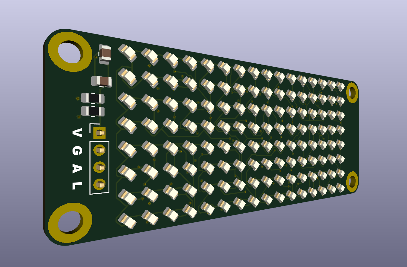
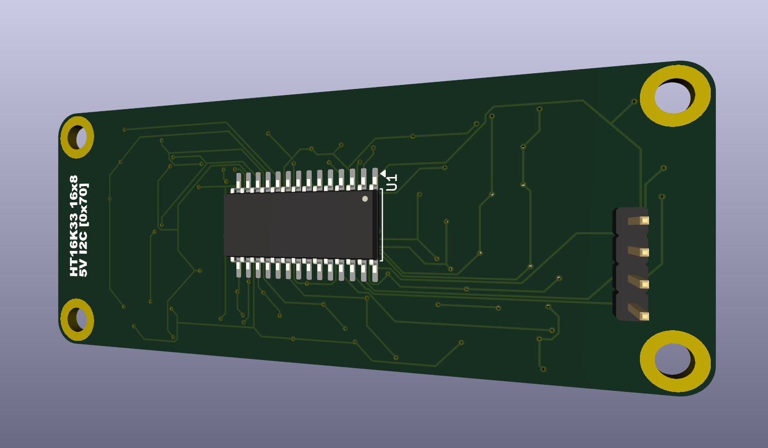
The PCB is approximately 74.93 mm wide and 30.48 mm high. It has rounded corners and four mounting holes, making it easy to attach behind an acrylic front panel or inside a small enclosure.
The 128 LEDs occupy most of the front surface. The LEDs are rotated approximately 45 degrees relative to the PCB edges, creating a diamond-shaped appearance for each illuminated point. The HT16K33 and the remaining components are positioned in the central and lower areas of the board.
Matrix Organization
Electrically, the display can be considered an 8-pixel-wide by 16-pixel-high matrix. For many applications, however, it is more convenient to treat the same hardware as a 16×8 landscape display.
The test firmware therefore provides both coordinate systems.
Physical orientation:

X = 0 ... 7
Y = 0 ... 15

Logical landscape orientation:

X = 0 ... 15
Y = 0 ... 7
The basic physical pixel function is:
void setPixel(int x, int y, bool state)
{
    if (x < 0 || x >= 8) return;
    if (y < 0 || y >= 16) return;

    uint8_t ramAddress;
    uint8_t bitNumber;

    if (y < 8)
    {
        ramAddress = (x * 2) + 1;
        bitNumber = 7 - y;
    }
    else
    {
        ramAddress = x * 2;
        bitNumber = 15 - y;
    }

    if (state)
        displayRAM[ramAddress] |= (1 << bitNumber);
    else
        displayRAM[ramAddress] &= ~(1 << bitNumber);
}
For normal 16×8 landscape graphics, I use a second function that translates the coordinates:
void setPixelLandscape(int x, int y, bool state)
{
    if (x < 0 || x >= 16) return;
    if (y < 0 || y >= 8) return;

    setPixel(y, 15 - x, state);
}
This means the application code can work with a familiar 16-pixel-wide display without having to know how the LEDs are physically connected to the HT16K33 display RAM.
HT16K33 Display RAM
The software keeps a local 16-byte framebuffer:
uint8_t displayRAM[16];
Once the framebuffer has been modified, the entire block can be sent to the controller:
void writeDisplay()
{
    Wire.beginTransmission(HT16K33_ADDR);
    Wire.write(0x00);

    for (int i = 0; i < 16; i++)
        Wire.write(displayRAM[i]);

    Wire.endTransmission();
}
Using a framebuffer makes animations much easier because an entire frame can be constructed in RAM before it is transferred to the display.
ESP32 Connection
The supplied test firmware uses the normal ESP32 I2C pins:
| ESP32 | Function |
|---|---|
| GPIO21 | SDA |
| GPIO22 | SCL |
#define HT16K33_ADDR 0x70

#define SDA_PIN 21
#define SCL_PIN 22

#define DEFAULT_BRIGHTNESS 8
The I2C interface is initialized at 100 kHz:
Wire.begin(SDA_PIN, SCL_PIN);
Wire.setClock(100000);
ESP8266 Connection
The same display routines can also be used with an ESP8266. Only the I2C pin definitions normally need to be changed.
For example, on many ESP8266 development boards:
#define SDA_PIN 4
#define SCL_PIN 5

Wire.begin(SDA_PIN, SCL_PIN);
These correspond to GPIO4 and GPIO5. Some development boards label these pins differently, so the GPIO numbers should always be checked for the particular ESP8266 board being used.
The same 3.3 V / 5 V I2C level-shifting consideration applies to the ESP8266.
HT16K33 Initialization
The test software initializes the display with only a few commands.
htCommand(0x21);   // Enable internal oscillator
htCommand(0x81);   // Display ON
setBrightness(DEFAULT_BRIGHTNESS);
clearDisplay();
The command helper function is:
void htCommand(uint8_t cmd)
{
    Wire.beginTransmission(HT16K33_ADDR);
    Wire.write(cmd);
    Wire.endTransmission();
}
Brightness Control
The HT16K33 provides hardware brightness control with sixteen available levels. The test program accepts values from 0 to 15.
void setBrightness(uint8_t b)
{
    if (b > 15) b = 15;
    htCommand(0xE0 | b);
}
This is useful for IoT devices that operate in different lighting conditions. For example, an LDR or ambient-light sensor could be connected to the ESP32 and used to automatically reduce the matrix brightness at night.
5×7 Character Font
The demonstration firmware also includes a simple 5×7 bitmap font for uppercase letters and numbers. Each character is stored as five columns of seven visible pixels.
The font currently includes:
- A–Z
- 0–9
- Space character
A character can be drawn directly into the framebuffer:
void drawCharLandscape(int px, int py, char c)
{
    for (int col = 0; col < 5; col++)
    {
        uint8_t bits = fontCol(c, col);

        for (int row = 0; row < 7; row++)
        {
            if (bits & (1 << row))
            {
                setPixelLandscape(
                    px + col,
                    py + row,
                    true
                );
            }
        }
    }
}
Scrolling Text
A 16×8 matrix is too narrow to display long words at once, but it is very suitable for horizontal scrolling text. The supplied demo scrolls:
HT16K33 DEMOacross the display using the 5×7 font.
void scrollText(const char *text)
{
    int len = strlen(text) * 6;

    for (int offset = 16; offset > -len; offset--)
    {
        clearBuffer();

        int x = offset;

        for (int i = 0; text[i]; i++)
        {
            drawCharLandscape(x, 0, text[i]);
            x += 6;
        }

        writeDisplay();
        delay(60);
    }

    clearDisplay();
}
Included Test Animations
I wrote a fairly extensive test program for checking the PCB, pixel mapping and animation performance. The main loop automatically cycles through several demonstrations.
| Demo | Purpose |
|---|---|
| All LED Test | Turns all 128 LEDs on and off |
| Brightness Demo | Fades through the available HT16K33 brightness levels |
| Row Scan | Checks every physical matrix row |
| Column Scan | Checks every physical matrix column |
| Snake Fill | Fills the complete matrix using a snake pattern |
| Scrolling Text | Displays horizontal 5×7 text |
| Vertical Text | Scrolls characters through the physical 8×16 orientation |
| Matrix Rain | Creates a falling-pixel Matrix-style animation |
| Smile | Displays a simple smile face |
| Sad Face | Displays a simple sad face |
| Heart Pulse | Uses hardware brightness control to create a pulsing heart |
| 8-Channel VU Meter | Uses the physical 8×16 orientation as eight vertical bars |
| 16-Channel VU Meter | Uses the landscape 16×8 orientation as sixteen level bars |
| Large Up Arrow | Scrolls a large arrow vertically |
| Scrolling Numbers | Displays large 8×12 style digits |
| Car Animation | Moves a small vehicle across the screen |
| Bouncing Ball | Single-pixel bouncing animation |
| Pong | Small automatic Pong animation |
| Arkanoid | Mini brick and paddle animation |
| Sine Wave | Animated mathematical wave |
| KITT Scanner | Moving scanner-style light effect |
| Spiral | Fills the 16×8 display using a spiral path |
All LED Test
The first test is deliberately simple. It turns every LED on for approximately 900 ms and then switches the matrix off.
void allLEDTest()
{
    setBrightness(8);

    allLED(true);
    delay(900);

    allLED(false);
    delay(300);
}
This is one of the most useful tests after assembling the PCB because missing, reversed or poorly soldered LEDs can immediately be identified.
Row and Column Tests
The row and column scan routines are useful for checking the electrical connections between the LEDs and the HT16K33. If one complete line fails to illuminate, the problem is more likely to be associated with a ROW or COM connection rather than with an individual LED.
Snake Fill Test
The snake animation lights each pixel sequentially while alternating direction on every row. Apart from being a simple animation, it is a very useful way of confirming that the logical pixel order matches the physical LED arrangement.
Matrix Rain
The Matrix-style rain effect uses a number of independently moving pixel heads with randomized starting positions and speeds. It demonstrates that the framebuffer can be updated fast enough for simple real-time animations without requiring complicated hardware.
Heart Pulse
The heart demo combines a bitmap graphic with the HT16K33 hardware brightness control. Instead of redrawing the graphic continuously, the heart remains stored in display RAM while the global brightness is increased and decreased.
VU Meter Examples
Both possible matrix orientations are useful for bar-graph applications.
In the 8×16 orientation, eight relatively tall channels can be displayed:
8 channels × 16 levelsIn landscape orientation, the same display can be used as:
16 channels × 8 levelsThis makes the PCB suitable for audio level displays, spectrum-style indicators, sensor arrays and status dashboards.
Large Numbers
The demo firmware also contains larger digit bitmaps for the numbers 1 through 9. Each character is approximately 8 pixels wide and 12 pixels high and is scrolled vertically through the physical 8×16 display area.
Large custom fonts can be useful for:
- Timers
- Counters
- Temperature displays
- Sensor values
- Production counters
- Simple digital clocks
Simple Games and Graphic Demos
A 16×8 display obviously has very limited resolution, but that limitation is also part of the fun. The test firmware contains automatic Pong and Arkanoid-style animations as well as a bouncing ball and moving car.
These examples are not intended to be complete games. They are simply useful demonstrations of coordinate mapping, animation timing and framebuffer updates.
Example Main Loop
The complete test program continuously cycles through all demonstrations:
void loop()
{
    allLEDTest();

    brightnessDemo();

    rowScan();

    columnScan();

    snakeFill();

    scrollText(" HT16K33 DEMO ");

    verticalText();

    matrixRain();

    smileEmoji();

    sadEmoji();

    heartPulse();

    vuMeter8();

    vuMeter16();

    bigUpArrow();

    scrollingNumbers();

    carDemo();

    bouncingBall();

    pongDemo();

    arkanoidDemo();

    sineWave();

    kittScanner();

    spiralDemo();

    delay(500);
}
Basic ESP32 Test Program Structure
For a real project it is not necessary to use all the demonstrations. The software can be reduced to a very small driver consisting of:
- I2C initialization
- HT16K33 command function
- 16-byte framebuffer
setPixel()writeDisplay()- Optional font and graphics functions
A minimal initialization sequence looks like this:
#include <Wire.h>

#define HT16K33_ADDR 0x70
#define SDA_PIN 21
#define SCL_PIN 22

uint8_t displayRAM[16];

void htCommand(uint8_t cmd)
{
    Wire.beginTransmission(HT16K33_ADDR);
    Wire.write(cmd);
    Wire.endTransmission();
}

void writeDisplay()
{
    Wire.beginTransmission(HT16K33_ADDR);
    Wire.write(0x00);

    for (int i = 0; i < 16; i++)
        Wire.write(displayRAM[i]);

    Wire.endTransmission();
}

void setup()
{
    Wire.begin(SDA_PIN, SCL_PIN);
    Wire.setClock(100000);

    delay(200);

    htCommand(0x21);
    htCommand(0x81);
    htCommand(0xE8);
}

void loop()
{
}
Possible IoT Applications
The display is intentionally generic. The HT16K33 only handles the LEDs, so the information shown on the panel can come from practically any ESP32 or ESP8266 application.
Some possible uses include:
- Wi-Fi clock
- NTP clock
- Scrolling message display
- MQTT status display
- Home Assistant indicator
- Weather information
- Indoor temperature and humidity
- Air-quality information
- Network status
- Server status
- Website statistics
- YouTube statistics
- Production counters
- Machine status indicators
- Battery level indicators
- Audio VU meters
- Simple spectrum displays
- Notification icons
- Custom symbols
- Small games and animations
Using the Panel with MQTT
One application I particularly like for this type of panel is a small MQTT-connected information display. An ESP32 can subscribe to one or more MQTT topics and convert the received information into text, icons or bar graphs.
For example:
home/livingroom/temperature
home/livingroom/humidity
home/security/status
home/internet/status
home/weather/condition
The display can then alternate between several pages or scroll the received information. Because the HT16K33 handles the multiplexing, the ESP32 remains free to manage Wi-Fi, MQTT, sensors and other application tasks.
Using Multiple Panels
Multiple matrices can also be placed next to each other to create a larger display. This requires each HT16K33 to use a different I2C address. The application can then treat several physical panels as one larger logical framebuffer.
For example, two panels can form:
32 × 8 pixelsand four panels can form:
64 × 8 pixelsor:
32 × 16 pixelsdepending on the physical arrangement.
Custom Graphics
Small monochrome icons are very easy to define as arrays or strings. For example, the supplied test program stores the heart as a small character map:
static const char *heart[] =
{
    " 11 11 ",
    "1111111",
    "1111111",
    "1111111",
    " 11111 ",
    "  111  ",
    "   1   "
};
The same technique can be used for Wi-Fi icons, battery symbols, arrows, weather icons or custom status indicators.
PCB Assembly
With 128 LEDs on a relatively small PCB, LED orientation is the most important part of assembly. A single reversed LED will remain dark even if the rest of the matrix is operating correctly.
My preferred assembly sequence is:
- Solder the HT16K33.
- Solder the two 4.7 kΩ resistors.
- Solder the 1 µF and 100 nF capacitors.
- Solder the four-pin connector.
- Install the 0805 LEDs in groups.
- Check LED polarity before continuing with the next group.
- Inspect all solder joints under magnification.
- Check VDD to GND resistance before applying power.
- Connect the controller through the appropriate I2C level interface.
- Run the all-LED test.
- Run the row and column scans.
- Run the snake test to confirm pixel order.
First Power-Up
Before connecting the ESP32, I recommend checking the PCB for shorts with a multimeter. Pay particular attention to the HT16K33 pins because the SOP package has a much finer pitch than the 0805 LEDs.
After the hardware has been checked, start with a simple I2C scanner. The HT16K33 should appear at:
0x70Once the device is visible on the bus, upload the test firmware. The first all-LED test immediately shows whether the matrix is basically functional.
Troubleshooting
HT16K33 is not detected at 0x70
- Check VDD and GND.
- Check SDA and SCL continuity.
- Check the 4.7 kΩ pull-up resistors.
- Check the I2C level shifter.
- Check for solder bridges around the HT16K33.
- Verify that SDA and SCL have not been swapped.
No LEDs illuminate
- Confirm that the HT16K33 oscillator has been enabled.
- Confirm that the display has been switched on with the display setup command.
- Check that display RAM is actually being written.
- Check the LED supply voltage.
- Check one LED manually for correct polarity.
One LED does not illuminate
- Check the LED orientation.
- Check both solder joints.
- Check for a damaged LED.
An entire row or column is missing
- Check the corresponding HT16K33 ROW or COM trace.
- Inspect the associated HT16K33 pin.
- Check for an open PCB trace or solder joint.
The image is mirrored or rotated
This normally means the electrical matrix is working correctly but the software coordinate mapping does not match the desired physical orientation. Modify the transformation inside setPixelLandscape() rather than changing every graphics routine.
The display works but the ESP32 becomes unstable
Check the SDA and SCL voltage levels. If the HT16K33 board is powered from 5 V and its pull-up resistors are also connected to 5 V, do not connect those lines directly to ESP32 or ESP8266 GPIO pins. Use a suitable bidirectional level translator.
Power Supply Considerations
The current required by the panel depends on the number of illuminated LEDs, the selected brightness level, LED characteristics and multiplexing duty cycle. For testing and normal IoT indicators, I generally do not need to operate the matrix at maximum brightness continuously.
A stable 5 V supply with enough current headroom should be used for the LED board. The ESP32 can use its normal regulated supply, with both sides sharing a common ground through the I2C level-shifting arrangement.
Why Use the HT16K33 Instead of Driving the LEDs Directly?
A 128-LED matrix could theoretically be multiplexed directly from a microcontroller, but doing so would require many GPIO pins, additional driver circuitry and continuous timing-sensitive refresh code.
With the HT16K33:
- The ESP32 only needs two communication signals.
- The LED refresh is performed in hardware.
- Display RAM is built into the driver.
- Brightness control is built into the driver.
- The application can spend its time on Wi-Fi, sensors, web services or MQTT instead of refreshing LEDs.
For an IoT project this separation is especially useful because display timing remains independent of network activity.
Ideas for Future Revisions
The current board is intentionally simple, but several additions could make a future version even more convenient.
- Integrated 3.3 V to 5 V bidirectional I2C level shifter
- Separate 3V3 and 5V connector pins
- I2C address configuration jumpers
- Input and output connectors for daisy chaining
- Integrated ambient-light sensor
- Alternative LED colors
- Different LED spacing
- Larger 32×8 modular versions
- Magnetic or threaded mounting options
- Acrylic front diffuser
This project started as a simple way of building my own 16×8 LED matrix instead of using a commercial module, but it turned into a useful general-purpose display platform.
With 128 individual 0805 LEDs, a compact HT16K33 driver and a simple I2C interface, the panel can be used for anything from basic status indicators to scrolling text, animated graphics, sensor dashboards, clocks, counters and Wi-Fi-connected IoT displays.
The test firmware intentionally contains many different animations because it also serves as a hardware diagnostic program. The all-LED, row, column and snake tests make it easy to verify a newly assembled PCB, while the text, graphics, VU meters and game demonstrations provide examples that can be reused in other projects.
The PCB, schematic, Gerber files and test firmware are included below so the project can be reproduced or modified for other applications.
Suggested Media for This Article
- Finished PCB front photograph
- Finished PCB rear photograph
- PCB schematic image
- Front copper / PCB layout image
- Rear copper / PCB layout image
- Short GIF of all LEDs
- Row scan GIF
- Column scan GIF
- Snake animation GIF
- Scrolling text GIF
- Matrix rain GIF
- Heart pulse GIF
- VU meter GIF
- Pong / Arkanoid GIF
- Full demonstration video
- ESP32 and display wiring photograph