
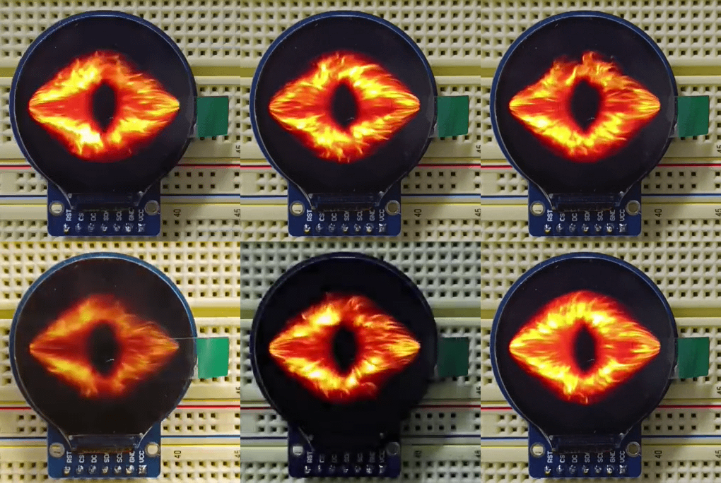
This project demonstrates how to create an animated Eye of Sauron using an ESP32 microcontroller and a 1.28-inch GC9A01 round TFT display.
Instead of playing animation frames from an external SD card, the entire animation is stored directly in the ESP32's internal flash memory as compressed JPEG images. The ESP32 decodes these frames and sends them to the round TFT display through a high-speed SPI interface.
The animation contains 240 individual frames at a resolution of 240×240 pixels, creating an approximately 30 FPS animation loop with a duration of 8 seconds.
I developed this project as an experiment in embedded graphics, flash-based animation playback, and circular display applications.
The final firmware also includes software brightness enhancement, a smooth startup fade-in effect, and continuously looping animation without intentionally restarting the fade effect between loops.
Sauron's Eye Animation – ESP32 with GC9A01 1.28" Round TFT Display
Main Features
-
ESP32-based microcontroller system
-
1.28-inch round TFT display
-
GC9A01 / GC9A01A display controller
-
240×240 pixel resolution
-
SPI communication
-
40 MHz SPI initialization
-
240 JPEG animation frames
-
8-second animation loop
-
30 FPS target playback
-
Animation stored entirely in internal flash memory
-
No external SD card required
-
No external storage or Wi-Fi connection required during playback
-
JPEG decoding using the JPEGDEC library
-
RGB565 color processing
-
140% software brightness enhancement
-
Smooth 2-second startup fade-in
-
Continuous animation playback
-
Serial monitoring of the actual displayed frame rate
Why I Built This Project
For this project, I wanted to reproduce the visual appearance of Sauron's Eye on a small, circular TFT display.
A round display is particularly interesting for animated eyes because it naturally matches the shape of the eye and provides a compact, self-contained visual effect.
Initially, one of the main challenges was deciding how to store and display a relatively large number of animation frames.
A conventional solution would be to store JPEG images or an animation file on a microSD card. However, I wanted to avoid additional hardware and keep the design as simple as possible.
The ESP32 provides enough flash storage for a short, efficiently compressed animation, so I converted the animation into a collection of JPEG frames and embedded them directly into the Arduino firmware.
This approach eliminates SD card communication, external file management, and the need for a filesystem during playback.
The ESP32 only needs to read the compressed frame data from flash, decode it, and transfer the resulting pixels to the TFT display.
Hardware Overview
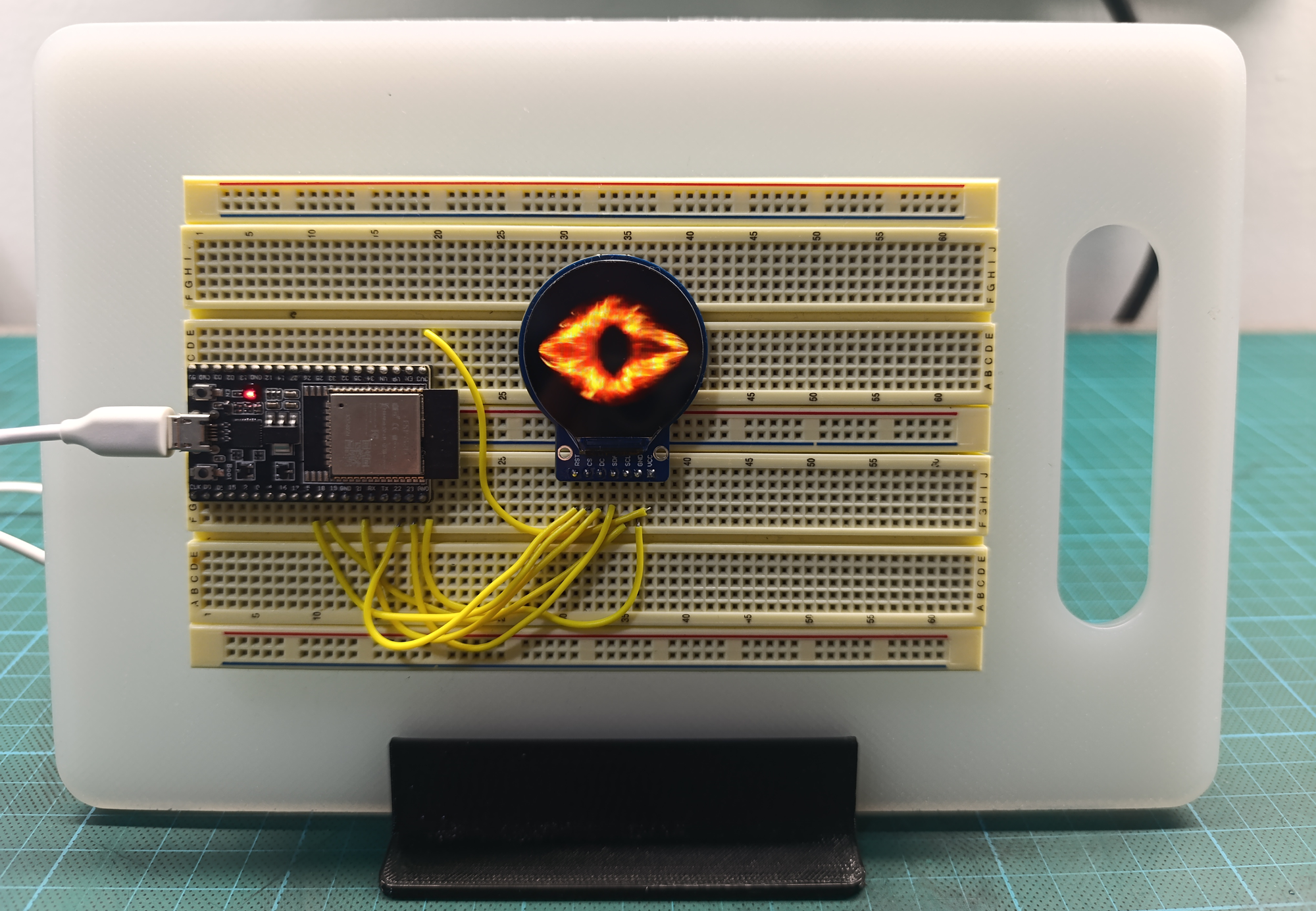
The hardware is intentionally simple. The project requires only an ESP32 development board, a GC9A01 round TFT display module, and a suitable power connection.
The ESP32 handles animation timing, JPEG decoding, brightness processing, and SPI communication.
The GC9A01 display controller receives the decoded RGB565 pixel data and updates the TFT panel.
Because the animation data is compiled into the firmware, no additional memory module or external storage interface is required.
Parts List (BOM)
| Component | Quantity | Description |
|---|---|---|
| ESP32 Development Board | 1 | ESP32-based board with sufficient flash and application partition space |
| GC9A01 Round TFT Display | 1 | 1.28-inch, 240×240 pixel SPI display |
| Jumper Wires | 1 set | Connections between ESP32 and TFT |
| USB Cable | 1 | ESP32 programming and power |
| 5 V USB Power Supply | 1 | Suitable regulated supply for the ESP32 board |
| Breadboard | Optional | For initial testing |
| Display Enclosure | Optional | For mounting the finished project |
The exact GPIO configuration in the supplied firmware uses the ESP32 VSPI peripheral.
The TFT module must have electrical compatibility with the selected ESP32 board. Many GC9A01 modules support 3.3 V logic, but their power input requirements can vary depending on the module design.
Always check the specifications of your particular TFT module before connecting the power supply.
ESP32 to GC9A01 Connection
The display communicates with the ESP32 using a four-wire SPI interface.
The firmware uses the following GPIO assignments:
| GC9A01 TFT Pin | ESP32 Pin | Function |
|---|---|---|
| SCL / SCK / CLK | GPIO18 | SPI Clock |
| SDA / DIN / MOSI | GPIO23 | SPI Data |
| CS | GPIO5 | Chip Select |
| DC / A0 | GPIO21 | Data / Command |
| RST / RES | GPIO22 | Display Reset |
| VCC | 3.3 V* | Display Power |
| GND | GND | Common Ground |
| BL / LED | Module-dependent | Backlight Supply / Control |
The VCC connection assumes a TFT breakout board designed for 3.3 V operation. Some modules include their own voltage regulator and specify a different power input. Follow the module manufacturer's instructions.
The backlight pin is not controlled separately by the supplied Arduino sketch. If your display includes a BL or LED input, connect or control it according to the module specifications.
Do not connect an unknown backlight input directly to an ESP32 GPIO without checking its electrical requirements.
Connection Diagram (Text)
ESP32 Development Board        GC9A01 Round TFT
------------------------------------------------
3.3V (if supported) ---------- VCC
GND -------------------------- GND

GPIO18 ----------------------- SCL / SCK
GPIO23 ----------------------- SDA / MOSI
GPIO5 ------------------------ CS
GPIO21 ----------------------- DC
GPIO22 ----------------------- RST

Backlight -------------------- As required by
                               TFT module
All ground connections must share a common reference.
The ESP32 GPIO signals operate at 3.3 V and must not be exposed directly to 5 V signals.
GC9A01 Display Configuration
The GC9A01 is a TFT LCD controller commonly found in compact 1.28-inch circular displays.
Although the display is physically circular, its graphics memory uses a conventional 240×240 coordinate system.
This allows normal rectangular JPEG images to be decoded and displayed without special circular framebuffer calculations.
Pixels outside the visible circular area are simply hidden by the physical display structure.
The Arduino sketch defines the display connections as follows:
#define TFT_SCLK 18
#define TFT_MOSI 23
#define TFT_CS    5
#define TFT_DC   21
#define TFT_RST  22
The display is initialized using the ESP32 VSPI interface:
SPIClass displaySPI(VSPI);

Adafruit_GC9A01A tft(
    &displaySPI,
    TFT_DC,
    TFT_CS,
    TFT_RST
);
The SPI interface is started with:
displaySPI.begin(
    TFT_SCLK,
    -1,
    TFT_MOSI,
    TFT_CS
);

tft.begin(40000000);
The value 40000000 configures a requested SPI frequency of 40 MHz.
Actual display transfer speed and animation performance depend on the ESP32, SPI implementation, and JPEG decoding workload.
Animation Specifications
The animation is supplied as a collection of compressed JPEG frames embedded inside a C/C++ header file.
| Parameter | Value |
|---|---|
| Display resolution | 240×240 pixels |
| Number of frames | 240 |
| Animation duration | 8000 ms |
| Target frame rate | 30 FPS |
| Image format | JPEG |
| Decoded pixel format | RGB565 |
| Frame storage | ESP32 internal flash |
| Compressed frame data | 910,450 bytes |
| External SD card | Not required |
The animation is designed to repeat continuously.
Its frame sequence is stored in the sauron_frames.h file.
Storing JPEG Frames in ESP32 Flash
One of the most important features of this project is that the entire animation is compiled directly into the firmware.
The header file contains three important elements.
First, the total number of frames:
static const uint16_t
SAURON_FRAME_COUNT = 240;
Second, the animation duration:
static const uint32_t
SAURON_DURATION_MS = 8000;
Third, two arrays containing JPEG frame data and frame offsets:
static const uint32_t
sauron_frame_offsets[241] PROGMEM = {
    // Frame offsets
};

static const uint8_t
sauron_jpeg_bytes[] PROGMEM = {
    // Compressed JPEG data
};
The JPEG data is stored as one continuous array rather than 240 separate files.
The offset table indicates where each JPEG frame begins and ends.
For example, the starting position of a frame is obtained using:
uint32_t start =
    sauron_frame_offsets[number];
Its compressed length is calculated using:
uint32_t length =
    sauron_frame_offsets[number + 1]
    - start;
This makes it possible to access any individual frame without reading or parsing a filesystem.
Why Use JPEG Compression?
A single uncompressed 240×240 RGB565 frame requires:
240 × 240 × 2 = 115,200 bytesFor 240 frames, the uncompressed animation would require:
115,200 × 240 = 27,648,000 bytesThat is approximately 26.37 MiB of raw pixel data.
The compressed JPEG animation data in this project occupies only 910,450 bytes, approximately 889 KiB.
This is a substantial reduction in flash storage requirements.
JPEG compression makes it practical to store a short, full-color animation inside an ESP32 firmware image.
The tradeoff is that the ESP32 must decode each frame before sending it to the display.
JPEG Decoding with JPEGDEC
The project uses the JPEGDEC library by Larry Bank.
Instead of decoding every image into a complete 240×240 framebuffer, the decoder processes JPEG data in smaller blocks.
These decoded blocks are transferred to the TFT display through SPI.
The firmware opens each JPEG directly from flash:
decoder.openFLASH(
    sauron_jpeg_bytes + start,
    length,
    drawJPEG
);
It then configures the RGB565 output format and decodes the image:
decoder.setPixelType(
    RGB565_LITTLE_ENDIAN
);

decoder.decode(0, 0, 0);
A custom callback function named drawJPEG() handles the decoded pixel blocks.
This function also applies software brightness enhancement and startup fading before sending the pixels to the display.
Processing JPEG blocks individually reduces the need for a full-frame RAM buffer.
RGB565 Color Processing
The GC9A01 display receives pixel data in RGB565 format.
Each pixel uses 16 bits:
-
5 bits for red
-
6 bits for green
-
5 bits for blue
The firmware separates these individual color components, modifies their values, and combines them back into RGB565 format.
This allows additional image processing without requiring a separate graphics-processing library.
Software Brightness Enhancement
The supplied firmware includes a software brightness enhancement setting:
constexpr uint32_t
BRIGHTNESS_PERCENT = 140;
This applies a 140% multiplier to the RGB565 color channels.
Each channel is limited to its maximum supported value to prevent numerical overflow.
For example, a red value is calculated using:
uint32_t r =
    (((c >> 11) & 0x1F)
    * BRIGHTNESS_PERCENT + 50) / 100;

if (r > 31) r = 31;
The same method is applied to the green and blue channels.
This processing increases the brightness of the image data, making darker colors more intense.
However, this is a software color enhancement rather than a hardware backlight adjustment.
It does not increase the physical brightness capability of the TFT backlight. Very bright color values may also become saturated.
Smooth Startup Fade-In
Another feature of this version is a smooth startup fade-in effect.
Instead of immediately displaying the animation at full intensity, the firmware gradually increases the pixel values over two seconds.
The fade duration is defined as:
constexpr uint32_t
FADE_IN_MS = 2000;
The firmware uses a smoothstep function to create a gradual transition:
float x =
    (float)elapsed / FADE_IN_MS;

float eased =
    x * x * (3.0f - 2.0f * x);
The result is converted into a brightness value between 0 and 255.
Each decoded pixel is then multiplied by this fade value.
The fade is applied only when the ESP32 starts.
Once the animation reaches full intensity, it continues looping without deliberately repeating the startup fade.
This is particularly useful for decorative electronics projects where the display should appear gradually rather than abruptly turning on.
Display Startup and Initialization
The firmware also contains startup handling intended to reduce unwanted visual effects during display initialization.
The TFT reset signal is asserted at the beginning of the setup routine.
After initializing the GC9A01 controller, the firmware sends the display-off command:
tft.writeCommand(0x28);The display memory is cleared to black:
tft.fillScreen(GC9A01A_BLACK);The first animation frame is then preloaded.
Finally, the display is enabled:
tft.writeCommand(0x29);This sequence helps establish a known initial display state before the normal animation playback begins.
It is important to understand that software cannot guarantee complete control over what the TFT shows before the ESP32 firmware starts running. The exact power-on behavior also depends on the display module and its hardware reset circuitry.
Animation Timing and Frame Selection
The animation playback is based on the elapsed time since startup.
Instead of simply waiting a fixed delay after displaying each frame, the firmware calculates which frame should currently be displayed.
The relevant calculation is:
uint16_t target =
    (uint16_t)(
        ((uint64_t)(
            elapsed % SAURON_DURATION_MS
        ) * SAURON_FRAME_COUNT)
        / SAURON_DURATION_MS
    );
This calculation maps the elapsed time to one of the 240 animation frames.
Because the animation duration is 8000 milliseconds, the nominal frame interval is:
8000 ms / 240 frames = 33.33 msThis corresponds to a target frame rate of 30 FPS.
If JPEG decoding or display transfers take longer than expected, the firmware can skip outdated frames and select the frame corresponding to the current animation time.
This approach helps maintain the intended 8-second animation period rather than allowing timing delays to accumulate.
The actual displayed frame rate depends on the available processing performance.
Continuous Animation Loop
The animation automatically repeats after eight seconds.
The firmware does not need to restart the display controller or reload the entire animation data.
It simply calculates the next frame number using the current playback time.
Once the elapsed time reaches the end of the animation period, the modulo operation returns the frame index to the beginning.
The supplied animation is intended for continuous playback. How smooth the transition appears depends on the visual continuity between the first and last frames.
The startup fade-in is controlled independently and is not repeated at each animation cycle.
Arduino IDE Software Requirements
The project was developed using the Arduino programming environment.
The following libraries are required.
| Library | Purpose |
|---|---|
| Arduino ESP32 Core | ESP32 board support |
| SPI | SPI communication |
| Adafruit GFX Library | Graphics support |
| Adafruit GC9A01A | Round TFT display driver |
| JPEGDEC by Larry Bank | JPEG image decoding |
Install the ESP32 board package through Arduino IDE Boards Manager.
Then install the required libraries using the Arduino Library Manager.
The libraries are included in the source code as follows:
#include <Arduino.h>
#include <SPI.h>
#include <Adafruit_GFX.h>
#include <Adafruit_GC9A01A.h>
#include <JPEGDEC.h>

#include "sauron_frames.h"
Because the JPEG frames are embedded in the header file, the project does not require an SD card library.
Arduino Project File Structure
The supplied project contains two source files.
SauronEye_NoStartBlink_140Brightness_v2/
│
├── SauronEye_NoStartBlink_140Brightness_v2.ino
│
└── sauron_frames.h
SauronEye_NoStartBlink_140Brightness_v2.ino
This is the main Arduino sketch.
It contains the display configuration, SPI initialization, JPEG decoding, RGB565 processing, brightness enhancement, startup fade-in, frame timing, and serial debugging functions.
sauron_frames.h
This header contains the 240 compressed JPEG animation frames.
It also defines the total frame count, animation duration, and frame offset table.
Both files must remain in the same Arduino sketch folder.
The header is required for compilation and cannot be replaced directly with an MP4 video file.
Flash Memory Requirements
Because all JPEG frames are embedded in the firmware, the compiled application requires more flash memory than a typical small Arduino sketch.
The compressed animation alone occupies approximately 889 KiB.
The complete firmware also includes program code, display libraries, JPEG decoding routines, and other compiled data.
A suitable ESP32 flash partition configuration must therefore provide enough application space for the complete binary.
For ESP32 development boards with 4 MB flash, a partition option such as Huge APP, when available for the selected board, may be useful.
The exact required application size should be checked from the Arduino IDE compilation output.
If compilation or uploading fails because the program is too large, review the selected flash size and partition scheme.
Changing the partition scheme does not physically increase the flash memory installed on the ESP32.
Uploading the Firmware
-
Connect the ESP32 development board to your computer using a USB cable.
-
Open Arduino IDE and select the appropriate ESP32 board and serial port.
-
Install the required display and JPEG libraries.
-
Extract the supplied ZIP archive.
-
Open
SauronEye_NoStartBlink_140Brightness_v2.ino. -
Make sure
sauron_frames.his in the same sketch folder. -
Verify that the TFT pin definitions match your hardware connections.
-
Select a flash partition configuration large enough for the application.
-
Compile and upload the firmware.
-
Open Serial Monitor at 115200 baud to inspect diagnostic messages.
After the ESP32 starts, it initializes the GC9A01 TFT, prepares the first animation frame, and begins playback.
No additional files need to be copied to an SD card or filesystem.
Serial Monitor Information
The firmware prints diagnostic information through the serial port.
The configured serial speed is:
Serial.begin(115200);The startup messages include the number of frames, display resolution, compressed frame data size, and startup fade settings.
The firmware also reports the measured displayed frame rate approximately every two seconds.
Example message format:
SAURON EYE - NO SD CARD - STARTUP FIX V2

Internal flash frames: 240 / 240x240 / ~30 fps
Flash data size: 910450 bytes
First frame preloaded: yes
Startup fade-in: 2000 ms, once only;
RGB brightness: 140%

Actual displayed FPS: ...
The actual FPS value depends on the hardware and decoding performance.
This diagnostic information is useful when testing SPI speed, image compression, and firmware changes.
Why Use a Round TFT Instead of an LED Matrix?
An LED matrix is useful for simple animations, symbols, and visual effects, but it has limited spatial resolution.
A 240×240 TFT display provides much more detail and supports full-color graphics.
The GC9A01 controller is especially suitable for this type of visual project because of its circular display area.
The TFT can reproduce detailed flames, shadows, color gradients, and moving textures that would be difficult to achieve using a small LED matrix.
The tradeoff is that TFT animation requires considerably more image data, flash memory, and processing power.
Using JPEG compression and the ESP32's SPI interface makes the design practical without adding external storage.
Troubleshooting
Display remains black
Check the power connection, common ground, SPI wiring, and backlight connection.
Verify that the TFT module uses a GC9A01-compatible controller and that its supply requirements match the wiring.
Also check the Serial Monitor for JPEG decoding errors.
Display shows incorrect colors
RGB565 byte ordering and pixel format configuration can affect the displayed colors.
The supplied firmware uses:
decoder.setPixelType(
    RGB565_LITTLE_ENDIAN
);
The display transfer code is configured for the decoded pixel format.
If you change the display library or decoding settings, the byte order may need to be reviewed.
Firmware is too large
The JPEG frame data occupies approximately 889 KiB before accounting for the rest of the application.
Select a suitable flash partition scheme and check the compiled binary size.
Animation does not reach 30 FPS
JPEG decoding performance depends on the ESP32 processor, compression complexity, library implementation, and SPI transfer speed.
The firmware targets 30 FPS, but the measured rate may be lower.
Check the FPS diagnostics in Serial Monitor.
Display flickers or behaves unexpectedly during startup
Check power stability, reset wiring, and the backlight circuit.
The supplied firmware includes display initialization handling and a one-time fade-in, but behavior before firmware execution also depends on the TFT module hardware.
Animation freezes
Check for JPEG decoding errors in the Serial Monitor.
Also verify that the animation header file is complete and matches the Arduino sketch.
Download Project Files
The complete Arduino project includes the main sketch and embedded animation data.
Arduino Source Code – ESP32 Sauron's Eye GC9A01
File: SauronEye_NoStartBlink_140Brightness_v2.zip
Contents:
-
SauronEye_NoStartBlink_140Brightness_v2.ino -
sauron_frames.h
The ZIP file contains the firmware source and all 240 JPEG frames required for animation playback.
Demonstration Video
File: barad_dur.mp4
A separate demonstration video can be included to show the visual theme of the project.
The Arduino firmware uses the precompiled animation data in sauron_frames.h rather than decoding the MP4 file directly.
Possible Improvements
The current firmware focuses on continuous animation playback using embedded JPEG frames.
Several additional features could be implemented in future versions:
-
Adjustable animation speed
-
Hardware PWM backlight brightness control
-
Ambient-light-based brightness adjustment
-
Different animation sequences
-
Capacitive touch control
-
Button-controlled animation selection
-
Custom startup effects
-
Alternative graphics and animated eyes
-
3D-printed enclosures
-
Circular or eye-shaped decorative front panels
For projects requiring much longer animations, an external SD card or larger flash memory could provide additional storage capacity.