
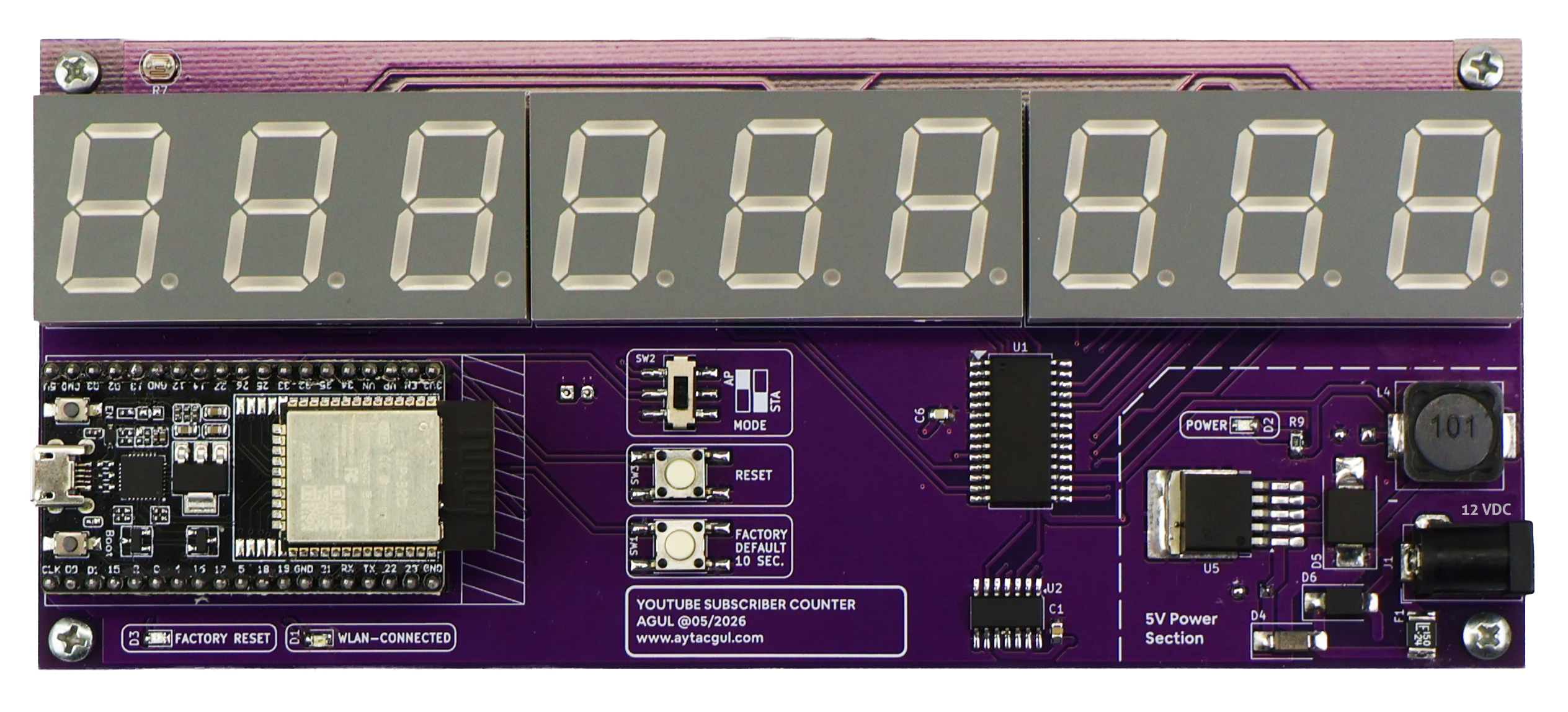
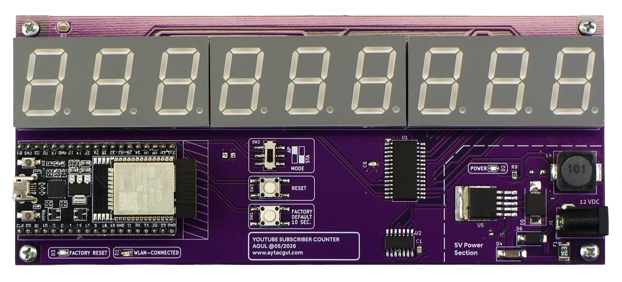
A standalone ESP32-based YouTube subscriber counter with three large 3-digit 7-segment displays, a TM1640 display driver, automatic brightness control, local web configuration.
I wanted to build a simple physical YouTube subscriber counter that could sit on a desk or shelf and continuously show the current subscriber count without needing a computer, browser, or phone.
The basic idea is simple: an ESP32 connects to Wi-Fi, reads the channel statistics from the YouTube Data API, and sends the subscriber count to a large 9-digit 7-segment display.
Instead of using ready-made display modules, I designed the display section around three 3-digit common-cathode LED displays driven by a TM1640. The ESP32 also hosts its own configuration page, so Wi-Fi credentials, YouTube API settings, channel information, and brightness can all be configured from a browser.
During testing I also ran into a small but interesting Wi-Fi problem. My main router and Xiaomi range extender both use the same SSID. An ESP32 normally connects using only the SSID and password, so it can sometimes choose the wrong access point. I eventually added BSSID and channel selection to the firmware, allowing the ESP32 to be locked to a specific router or extender.
The result is this little project.
Main features
- ESP32 based controller
- TM1640 LED display driver
- Three 3-digit common-cathode 7-segment displays
- 9-digit total display capacity
- YouTube subscriber count over the YouTube Data API
- Local browser-based configuration page
- AP and Client operating modes
- Automatic Wi-Fi network scanning
- SSID, BSSID, Wi-Fi channel, and RSSI display
- Optional BSSID locking for networks with multiple access points using the same SSID
- Automatic Wi-Fi reconnection
- mDNS support using
ytb-counter.local - LDR-based automatic display brightness
- Manual brightness control from 0 to 100%
- YouTube API test directly from the configuration page
- Channel ID and YouTube handle support
- Restart and factory-reset button
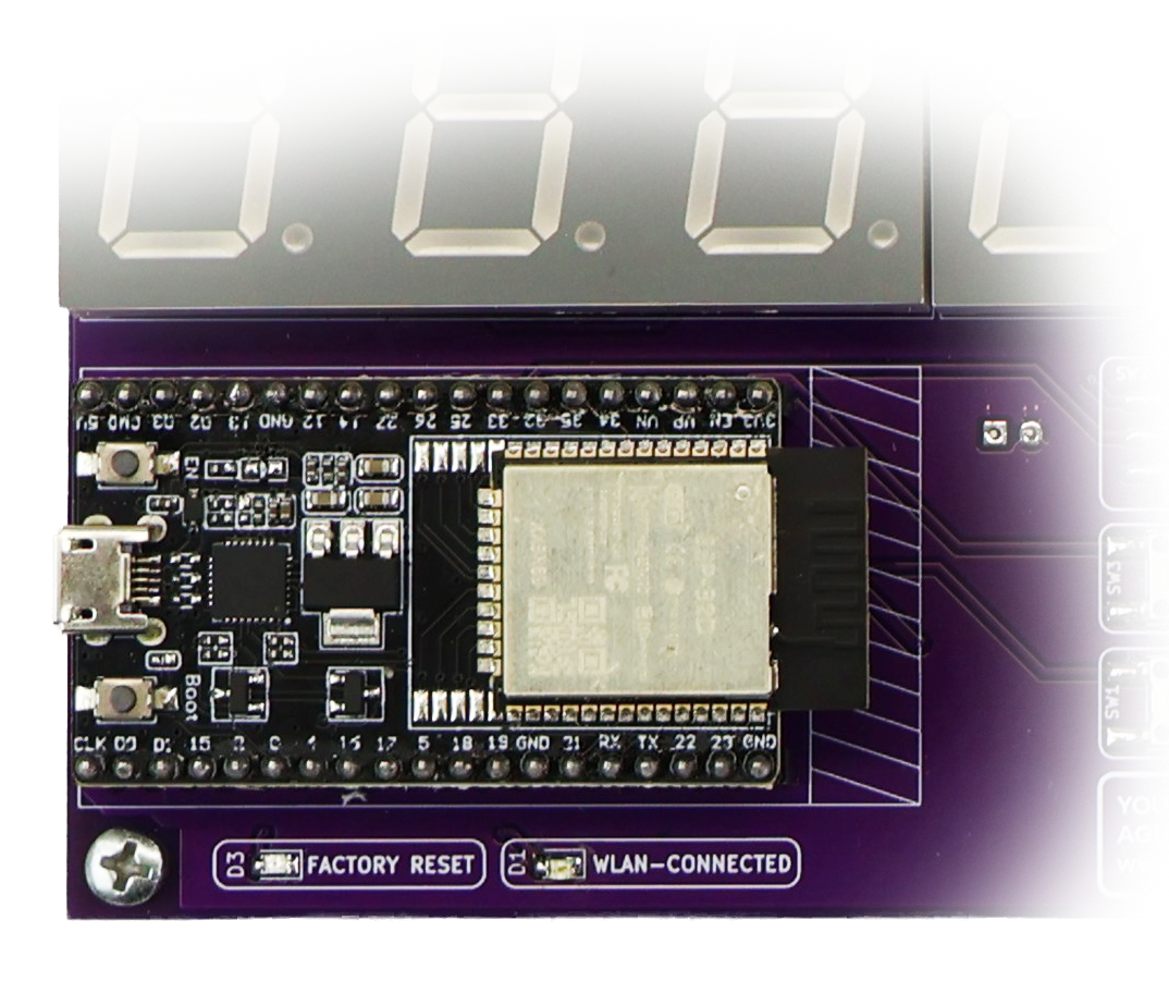
- WLAN status LED
- Non-volatile settings storage using ESP32 Preferences
Hardware overview
The main controller is an ESP32. I used the ESP32 because it provides Wi-Fi, enough GPIO, non-volatile storage, ADC inputs, and enough processing power to run the display and web interface at the same time.
The display itself consists of three 3-digit common-cathode 7-segment modules. Together they give me nine digits, which is more than enough for the intended subscriber counter.
A TM1640 handles the LED multiplexing. This greatly simplifies the ESP32 side because only a clock and data connection are required instead of directly multiplexing all display segments from the microcontroller.
| Component | Function |
|---|---|
| ESP32 | Main controller, Wi-Fi, web server, YouTube API communication, brightness control |
| TM1640 | Multiplexed 7-segment LED display driver |
| 3 × 3-digit 7-segment display | 9-digit subscriber count display |
| SN74HCT125 | Buffer / logic interface between the ESP32 and TM1640 |
| LDR | Ambient-light measurement for automatic brightness |
| LM2576S-5 | 5 V buck regulator for the display and controller power supply |
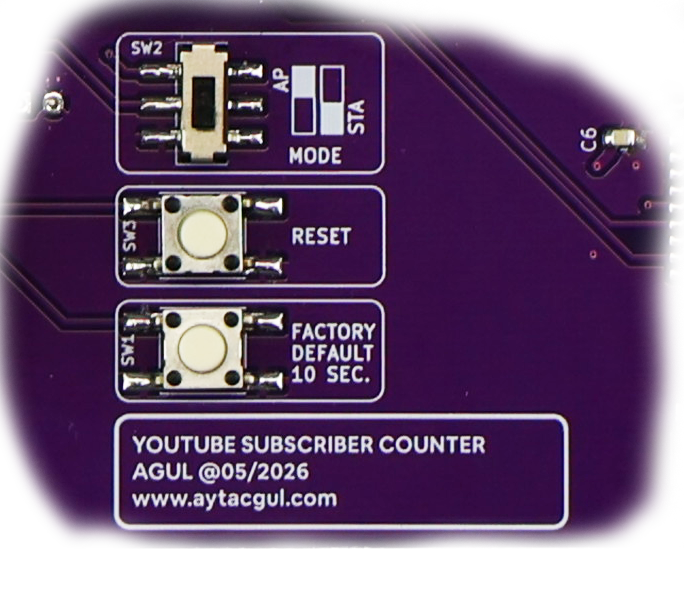
| Mode selector | Selects configuration AP mode or normal Client mode |
| Factory / restart button | Restarts the controller or clears stored settings |
Power supply
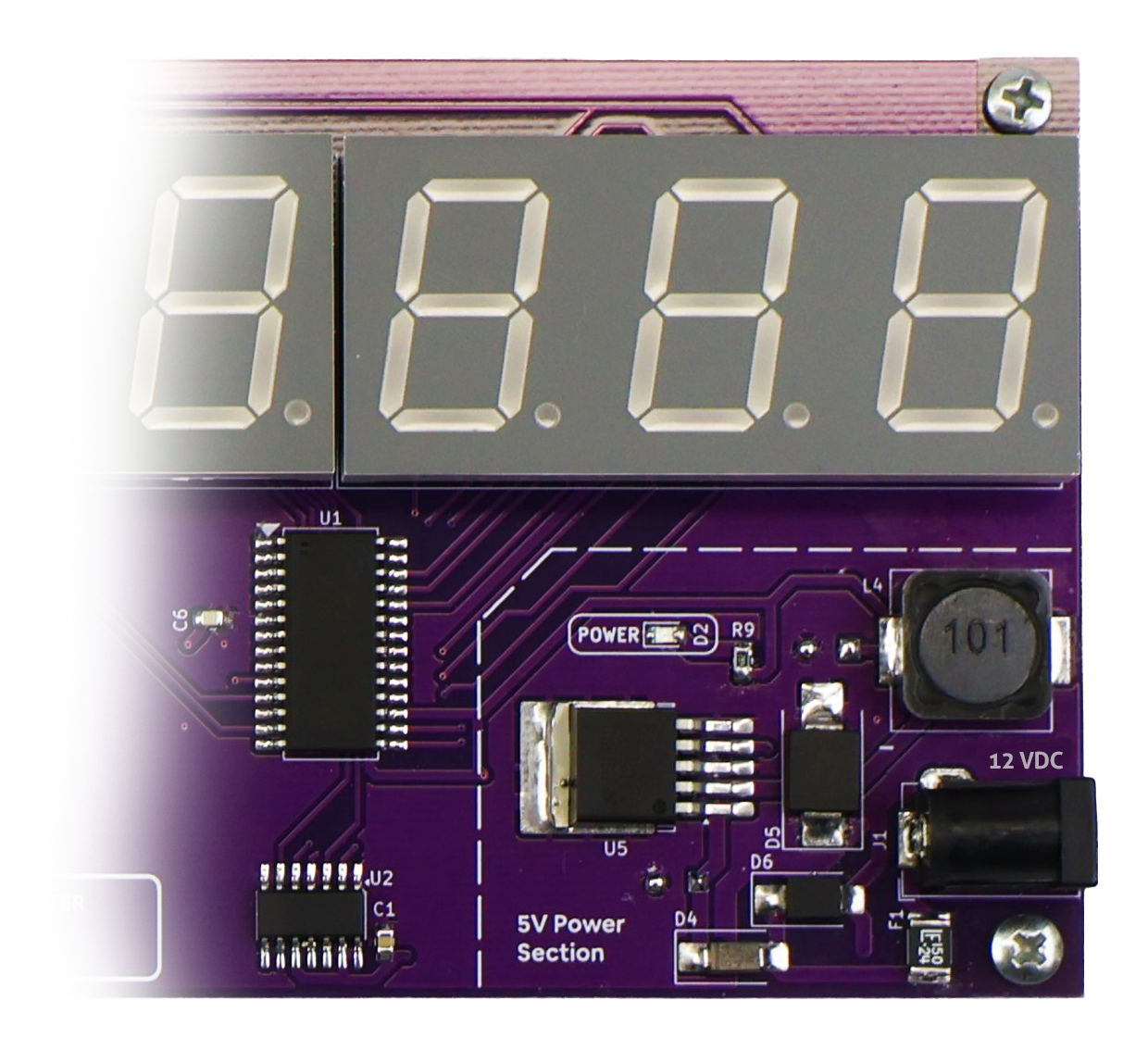
I wanted the counter to work from a normal external DC adapter, so the board includes its own 5 V switch-mode power supply rather than relying entirely on the ESP32 development board regulator.
The power section is built around an LM2576S-5 buck converter with a 100 µH inductor, SS34 Schottky diode, input and output bulk capacitors, and local decoupling.
I also added basic input protection:
- Resettable input fuse
- Series Schottky diode for reverse-polarity protection
- TVS diode on the DC input
- Input bulk capacitor
- Output bulk capacitor
- 100 nF local decoupling capacitors
An additional Schottky diode isolates the board's 5 V supply from the ESP32 5 V input, which helps prevent unwanted backfeeding when the ESP32 is connected to USB during programming.
ESP32 pin mapping
| ESP32 GPIO | Function |
|---|---|
| GPIO16 | TM1640 DIN |
| GPIO17 | TM1640 CLK |
| GPIO33 | AP / Client mode selector |
| GPIO32 | Restart / factory-reset button |
| GPIO26 | WLAN status LED |
| GPIO27 | Factory-reset status LED |
| GPIO34 | LDR analog input |
TM1640 display mapping
The physical display order on my PCB is:
L1: D1 D2 D3 | L2: D1 D2 D3 | L3: D1 D2 D3Because of the way the PCB traces were routed, the TM1640 grid order is not the same as the logical left-to-right digit order.
The firmware therefore contains a small translation table:
Logical digit 0 -> GRID7
Logical digit 1 -> GRID8
Logical digit 2 -> GRID9

Logical digit 3 -> GRID4
Logical digit 4 -> GRID5
Logical digit 5 -> GRID6

Logical digit 6 -> GRID1
Logical digit 7 -> GRID2
Logical digit 8 -> GRID3
Logical digit 0 is the rightmost digit, so the firmware can treat the display as a normal 9-digit number even though the physical wiring order is different.
Why I used the TM1640
Driving nine 7-segment digits directly from the ESP32 would require many GPIO pins and continuous multiplexing in firmware.
The TM1640 handles both segment and digit multiplexing internally. From the ESP32 side I only need a two-wire write-only interface.
The firmware writes a 16-byte display RAM image to the TM1640 and lets the driver handle the multiplexing.
Another useful feature is hardware brightness control. The TM1640 has eight display brightness levels, which I map to a user-friendly 0-100% slider in the web interface.
Automatic brightness
There is an LDR on the PCB connected to an ESP32 ADC input through a resistor divider.
In automatic mode the firmware reads the ambient-light level approximately every 200 ms and changes the TM1640 brightness accordingly.
In a bright room the display becomes brighter. In a dark room the brightness is reduced so the display does not become distracting.
Automatic brightness is enabled by default.
If I disable it from the web interface, a manual 0-100% brightness slider becomes available. The default manual value is 80%.
I deliberately made 0% correspond to the lowest visible TM1640 brightness level rather than turning the display completely off. This means the subscriber count is still visible even with the slider at its minimum position.
AP and Client modes
I wanted configuration to be possible without recompiling the firmware every time the Wi-Fi network or YouTube channel changes.
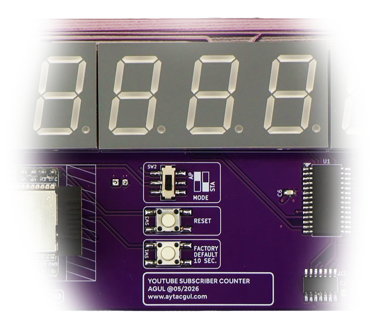
The PCB therefore has a physical mode selector.
| Mode | Behavior |
|---|---|
| AP Mode | ESP32 creates its own Wi-Fi network and opens the configuration interface |
| Client Mode | ESP32 connects to the saved Wi-Fi network and periodically reads the subscriber count |
Setup access point
In AP mode the ESP32 creates:
SSID: YTB-COUNTER
Password: 123456789
IP Address: 192.168.4.1
The ESP32 also runs a small captive-portal DNS server. On many phones and computers the configuration page therefore opens automatically after connecting to the setup network.
If it does not open automatically, I can simply enter:
192.168.4.1Web configuration
The configuration page is generated directly by the ESP32. There is no external web server and no cloud configuration service.
From the page I can configure:
- Wi-Fi network
- Wi-Fi password
- YouTube API key
- YouTube channel ID or handle
- Automatic brightness
- Manual brightness
There is also a YouTube Test button. This performs an API request immediately and reports whether the Wi-Fi connection, API key, and channel configuration are working.
Handling routers and range extenders with the same SSID
This became one of the more interesting parts of the firmware.
My main router and Xiaomi range extender both broadcast the same Wi-Fi name. For example:
SSID: MYSSID
Main Router:     MYSSID
Range Extender:  MYSSID
Normally an ESP32 connection can be started with only:
WiFi.begin(ssid, password);That tells the ESP32 which network name to use, but it does not specify which physical access point should be selected.
Two access points can therefore have the same SSID while having completely different BSSID addresses and possibly different Wi-Fi channels.
The firmware now lists each detected access point separately:
MYSSID | -42 dBm | CH 6  | AA:BB:CC:DD:EE:01
MYSSID | -61 dBm | CH 11 | AA:BB:CC:DD:EE:02
When I select one of them, the firmware stores:
- SSID
- Password
- BSSID
- Wi-Fi channel
The ESP32 can then connect specifically to that access point instead of randomly choosing between several devices advertising the same SSID.
This is especially useful with repeaters, range extenders, and installations with multiple access points.
Persistent settings
Configuration is stored using the ESP32 Preferences library, so removing power does not erase the setup.
The firmware stores:
- Wi-Fi SSID
- Wi-Fi password
- Selected BSSID
- Selected Wi-Fi channel
- YouTube API key
- YouTube channel ID
- Brightness mode
- Manual brightness setting
Local hostname and mDNS
When the counter is connected to the local network, the router assigns it a normal DHCP IP address such as:
192.168.1.86I can always use that IP address to open the settings page.
The firmware also starts an mDNS responder using the hostname:
ytb-counter.localOn networks where mDNS is supported, this means I can open the configuration page without remembering the ESP32 IP address.
I also added mDNS recovery to the firmware. If Wi-Fi disconnects, the previous mDNS responder is stopped. When Wi-Fi reconnects or the ESP32 receives a new IP address, mDNS is started again.
ytb-counter.local does not work.Client-mode startup
When the ESP32 starts in Client mode it connects to the saved network and receives an IP address using DHCP.
Because a 7-segment display is not suitable for showing a full IP address, I display the last octet for approximately three seconds during startup.
For example, if the assigned address is:
192.168.1.86the display briefly indicates:
SET IP 86After that, normal subscriber-count operation starts.
Reading the YouTube subscriber count
The ESP32 communicates directly with the YouTube Data API using HTTPS.
The firmware requests the statistics for the configured channel, extracts the subscriber count from the returned JSON data, and sends the result to the TM1640 display.
Subscriber data is requested approximately every 10 seconds.
The request flow is approximately:
ESP32
  |
  +-- Connect to Wi-Fi
  |
  +-- Connect to YouTube API using HTTPS
  |
  +-- Request channel statistics
  |
  +-- Parse JSON response
  |
  +-- Extract subscriberCount
  |
  +-- Update TM1640 display
  |
  +-- Wait for next update
Channel ID and handle support
The settings page accepts either a normal YouTube channel ID or a channel handle.
For example:
UCxxxxxxxxxxxxxxxxxxxxxx

or

@mychannel
If I enter a handle, the firmware first resolves it to the corresponding channel ID. The resolved ID is then saved in Preferences and used for future statistics requests.
Network and API error handling
A permanently connected display should not become useless just because the internet connection disappears for a few seconds.
The firmware therefore keeps the last successfully received subscriber count in memory.
If a request fails, the display briefly shows an error message. When possible, it then returns to the most recent valid subscriber count.
| Display message | Meaning |
|---|---|
no WiFi |
ESP32 is not connected to Wi-Fi |
API Err |
YouTube API configuration is missing or invalid |
Ht... |
HTTP error returned by the server |
Chan Err |
Channel could not be resolved |
Net Err |
Network or response parsing error |
Wi-Fi reconnection
The firmware continuously checks the station connection while operating in Client mode.
If Wi-Fi is lost, it periodically attempts to reconnect using the stored network configuration. When a BSSID and channel have been saved, the reconnect attempt remains locked to that specific access point.
Once the connection is restored, the device resumes YouTube updates automatically.
Factory reset and restart button
I wanted the device to remain usable even if an incorrect Wi-Fi password or API configuration is stored.
The button therefore has two functions:
| Button action | Result |
|---|---|
| Short press | Restart ESP32 |
| Hold for approximately 10 seconds | Erase stored settings and perform a factory reset |
During a factory reset the status LED flashes three times before the ESP32 restarts.
Firmware flow summary
| State | What happens |
|---|---|
| Power on | Initialize TM1640, GPIO, brightness, Wi-Fi, web server, and saved settings |
| AP mode | Create YTB-COUNTER setup network and run captive configuration portal |
| Client mode | Connect to the selected Wi-Fi access point |
| Wi-Fi connected | Start web server and mDNS responder |
| Startup | Show the final octet of the DHCP IP address for approximately three seconds |
| Normal operation | Request subscriber count approximately every 10 seconds |
| Valid response | Update the 9-digit display |
| API / network error | Show an error message and retain the previous valid count when available |
| Wi-Fi lost | Attempt automatic reconnection |
| Wi-Fi restored | Restart mDNS if necessary and continue normal operation |
Arduino libraries
The firmware uses the standard ESP32 Arduino networking libraries together with ArduinoJson.
#include <WiFi.h>
#include <WebServer.h>
#include <DNSServer.h>
#include <Preferences.h>
#include <HTTPClient.h>
#include <WiFiClientSecure.h>
#include <ArduinoJson.h>
#include <ESPmDNS.h>
Initial setup
The normal setup procedure is:
- Upload the firmware to the ESP32.
- Move the hardware selector to AP mode.
- Restart the device.
- Connect a phone or computer to
YTB-COUNTER. - Open the configuration page.
- Select the Wi-Fi access point.
- Enter the Wi-Fi password.
- Enter the YouTube API key.
- Enter the YouTube channel ID or handle.
- Press YOUTUBE TEST to verify the configuration.
- Save the settings.
- Move the selector to Client mode.
- Restart the device.
After connecting to the router, the display briefly shows its IP information and then starts displaying the subscriber count.
Using the same SSID on a router and extender
If there is only one access point for an SSID, simply select it normally.
If several access points use the same name, look at the BSSID, channel, and RSSI values in the Wi-Fi list.
I normally identify the router I want to use and select that exact entry. The ESP32 saves its BSSID and channel, so subsequent connections go back to the same physical access point.
Things I deliberately kept simple
There is no external application, MQTT broker, Home Assistant dependency, database, or custom cloud service in this project.
Once configured, the only external service required for normal operation is the YouTube API.
The ESP32 itself handles:
- Configuration
- Wi-Fi management
- Persistent storage
- HTTPS requests
- JSON parsing
- Display control
- Brightness management
- Local web interface
That was exactly what I wanted: a display that I could power on, leave on a shelf, and mostly forget about.
Possible modifications
Although I built this specifically as a YouTube subscriber counter, most of the hardware can be reused for other network-connected counters.
With firmware changes, the same board could display things such as:
- YouTube view count
- Website visitor statistics
- GitHub stars
- Social-media statistics
- Production counters
- Sensor values
- Home-automation information
- Any numeric value available through an HTTP API
The TM1640 and 9-digit display section does not care where the number comes from, so the project is also a useful general-purpose ESP32 network display platform.