
A simple, battery-powered Geiger counter built around the cheapest Geiger tube I could find.
Radiation detection has always been one of those projects that feels a little magical. You cannot see radiation, you cannot smell it, and in everyday life you rarely have any indication that it is even there. Yet with a Geiger counter, invisible ionizing particles suddenly become audible through a stream of clicks.
This project started with a simple goal: build a practical Geiger counter at the lowest possible cost .
Instead of using expensive SBM-20 or Western Geiger tubes, I chose the SI3BG (СИ-3БГ) Soviet Geiger-Müller tube. The reason was straightforward: it was the cheapest tube available in quantity, often costing significantly less than more popular alternatives.
The result is a compact handheld Geiger counter powered by three AA batteries, capable of displaying both CPM (Counts Per Minute) and µSv/h (Microsieverts per hour) on a four-digit LED display while providing classic Geiger click sounds through a piezo buzzer.
Why Build Another Geiger Counter?
There are already many Geiger counter designs on the internet.
Most of them fall into one of two categories:
- Extremely simple click-only circuits
- Complex devices with LCD displays, USB interfaces, data logging, Bluetooth, and PC software
I wanted something in between.
The design goals were:
- Low component count
- Inexpensive Geiger tube
- Easily obtainable parts
- Long battery life
- Audible clicks
- Numerical display
- No specialized parts
- Through-hole Geiger tube
- Easy to assemble
The finished device can be built entirely from commonly available components and inexpensive PCB fabrication services.
The SI3BG Geiger Tube
The heart of the project is the Soviet-era SI3BG (СИ-3БГ) Geiger-Müller tube.
Many hobbyists automatically choose the SBM-20 because it is well known, but SI3BG tubes are often available at a much lower price.
That was the primary reason I selected it.
The tube works similarly to other Geiger-Müller tubes:
- Requires approximately 380–450V bias
- Produces short discharge pulses when radiation is detected
- Very low operating current
- Long service life
Because the project was intended to be low-cost, using the least expensive tube available made the most sense.
Hardware Overview
The counter consists of four main sections:
| Section | Purpose |
|---|---|
| High-voltage generator | Produces Geiger tube bias voltage |
| Pulse detector | Converts tube pulses into logic signals |
| ATmega168 | Processes counts and calculates values |
| TM1638 display driver | Drives the 4-digit LED display |
The entire system runs from:
3 × AA batteries (4.5V nominal)
No lithium batteries, charging circuits, or USB power supplies are required.
Simply insert batteries and switch it on.
High Voltage Supply
One of the most interesting parts of any Geiger counter is the high-voltage generator.
The SI3BG tube requires several hundred volts, while the batteries only provide 4.5V.
To bridge this gap, the design uses a switching boost converter followed by a voltage multiplier network. The schematic shows a transistor-driven oscillator feeding an inductor and diode/capacitor cascade to generate the tube bias voltage.
The converter operates continuously while consuming surprisingly little power because Geiger tubes require very little current.
A trimmer potentiometer allows adjustment of the generated voltage during calibration.
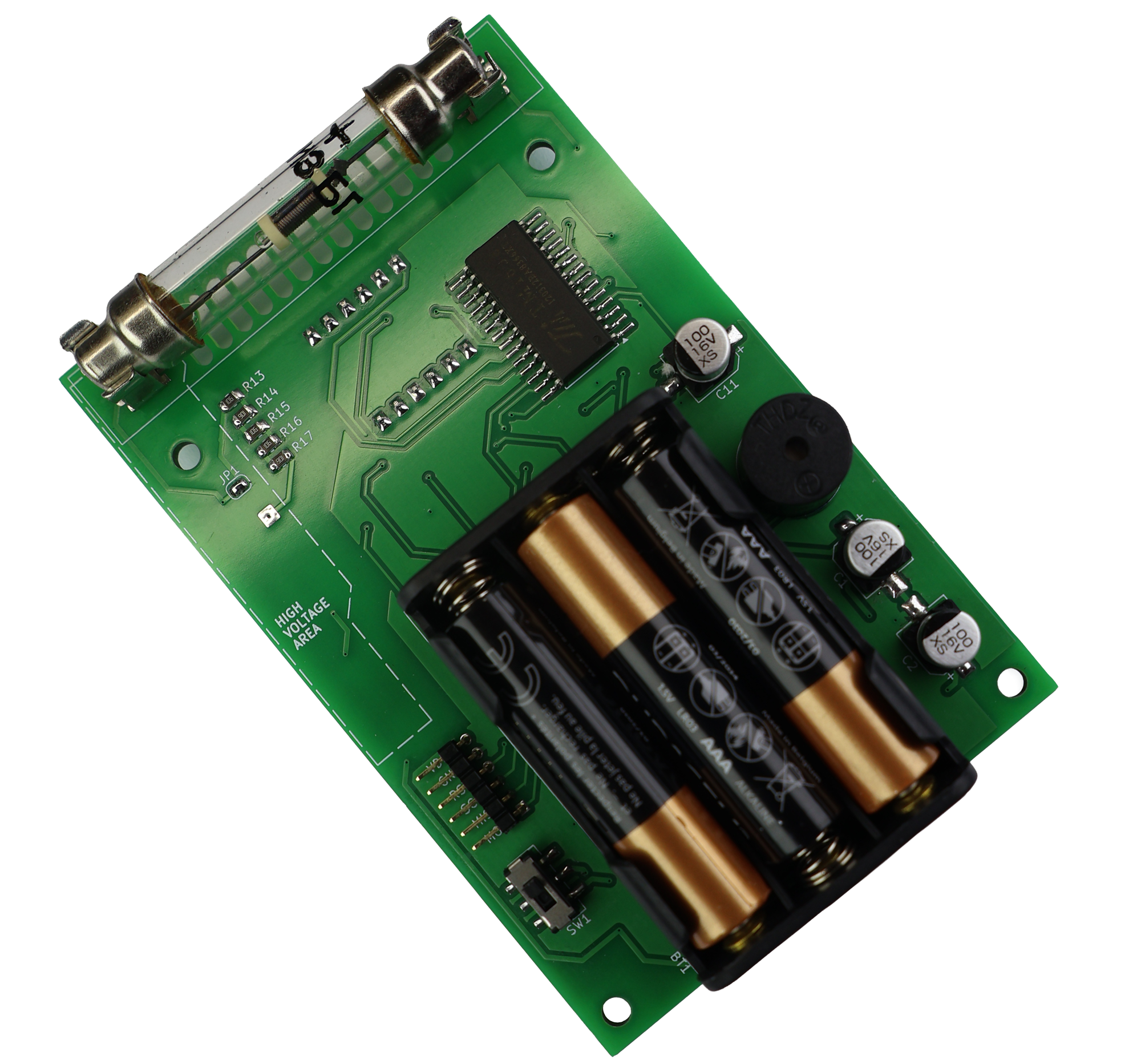
The PCB even includes a clearly marked:
"HIGH VOLTAGE AREA"
to remind users that several hundred volts are present, despite the device being battery powered.
Fortunately, the available current is extremely small.
You may feel a small shock if you touch the wrong place, but the energy is very limited.
Still, caution is recommended.
Pulse Detection
When ionizing radiation enters the tube, a brief avalanche discharge occurs.
These discharge pulses are extremely short and cannot be connected directly to a microcontroller.
The detector stage performs several functions:
- Receives pulses from the Geiger tube
- Filters noise
- Shapes pulse timing
- Produces clean digital pulses
The pulse processing section uses a pair of timer/comparator stages to create reliable counting pulses before they reach the microcontroller.
This significantly improves noise immunity compared to directly sampling the tube output.
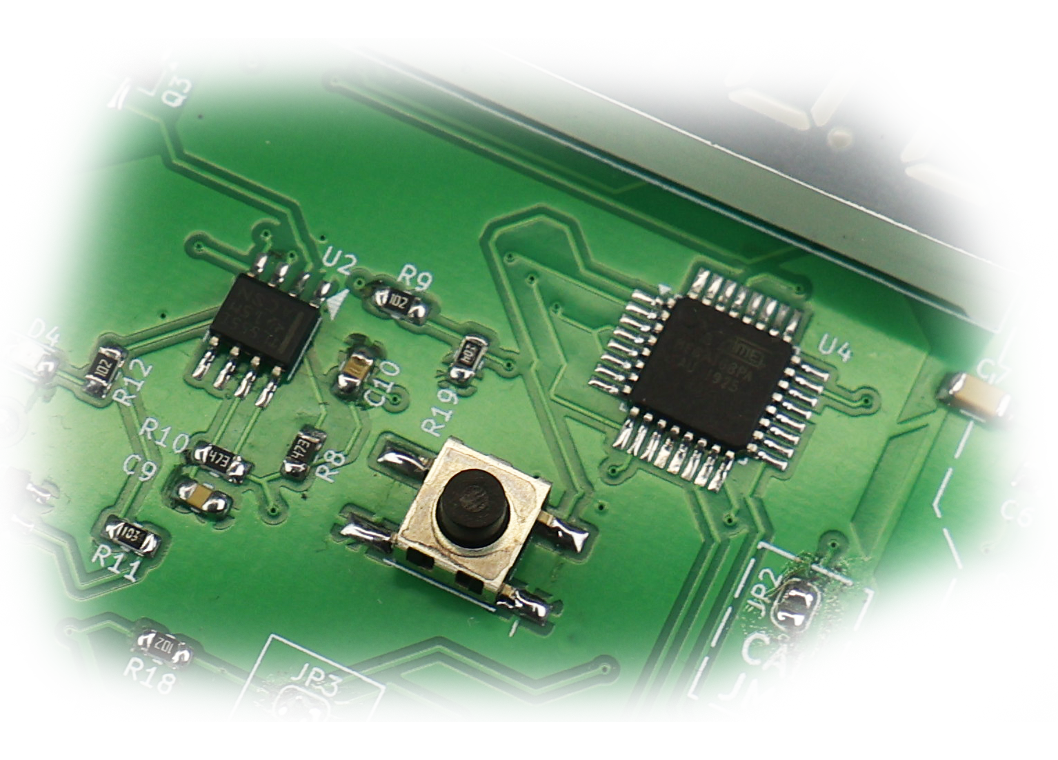
Microcontroller
The brain of the project is an:
ATmega168PA
I selected it simply because it is inexpensive, widely available, and more than capable of handling the required calculations.
The firmware performs:
- Pulse counting
- CPM calculation
- Dose rate estimation
- Display updates
- Button handling
- Audible click generation
- Mode switching
An ATmega328P would also work with only minor firmware changes.
Display
For display output I used a:
TM1638 LED driver
driving a four-digit seven-segment display.
I have used TM1638-based designs in several projects because they dramatically reduce I/O requirements.
Instead of dedicating many GPIO pins to the display, the ATmega communicates through a simple serial-style interface.
The display can show:
| Mode | Example |
|---|---|
| CPM | 0123 |
| CPM | 1450 |
| µSv/h | 0.15 |
| µSv/h | 2.30 |
The user can switch between display modes using the tactile push button.
User Interface
I wanted the interface to remain extremely simple.
There is only one button.
Pressing the button changes the display mode.
The device alternates between:
CPM Mode
Counts Per Minute.
This is the raw Geiger tube count rate.
Useful for:
- Tube characterization
- Radiation source comparison
- General detector performance
µSv/h Mode
Estimated dose rate.
This is usually more meaningful for casual users because it represents radiation levels in familiar units.
The firmware applies a conversion factor appropriate for the SI3BG tube.
The Geiger Click
No Geiger counter feels complete without the classic clicking sound.
Each detected pulse generates a short click on the piezo buzzer.
The sound is generated directly by the microcontroller.
Low radiation environments produce occasional clicks.
Near a radioactive source the clicks become increasingly frequent.
That sound is one of the reasons Geiger counters are so fascinating. You can literally hear radiation.
Firmware Operation
The software is intentionally straightforward.
The main loop continuously monitors incoming pulse events and updates display information.
Startup Sequence
| Step | Action |
|---|---|
| 1 | Power applied |
| 2 | Hardware initialization |
| 3 | Display startup |
| 4 | HV generator stabilizes |
| 5 | Pulse counting begins |
Radiation Detection Flow
| Event | Action |
|---|---|
| Tube pulse occurs | Pulse detector triggers |
| ATmega receives interrupt | Count incremented |
| Piezo click generated | Audible feedback |
| Display refreshed | Current values updated |
Display Flow
| Button State | Display |
|---|---|
| Default | CPM |
| Button press | µSv/h |
| Next press | CPM |
Power Consumption
One of the original goals was battery operation.
Using three AA batteries offers several advantages:
- Easy to obtain
- Low cost
- Long shelf life
- No charging circuitry required
Because the Geiger tube itself consumes almost no current, most power consumption comes from:
- Display
- High-voltage converter
- Microcontroller
Battery life depends heavily on display brightness and usage patterns.
Calibration
A Geiger counter is only as useful as its calibration.
The PCB includes:
- HV adjustment trimmer
- Calibration jumper
- Test points
These features simplify setup and verification.
The high-voltage adjustment should be performed carefully using an appropriate high-voltage measurement method.
Why Not Use an SBM-20?
This is probably the question I receive most often.
The answer is simple:
Cost.
The SI3BG tube was chosen because it was the least expensive Geiger tube I could reliably obtain.
For a project intended to be a genuinely low-cost Geiger counter, that mattered more than absolute sensitivity.
The device still performs well enough for:
- Background radiation monitoring
- Educational demonstrations
- Radioactive mineral detection
- Experimentation
- Learning about radiation
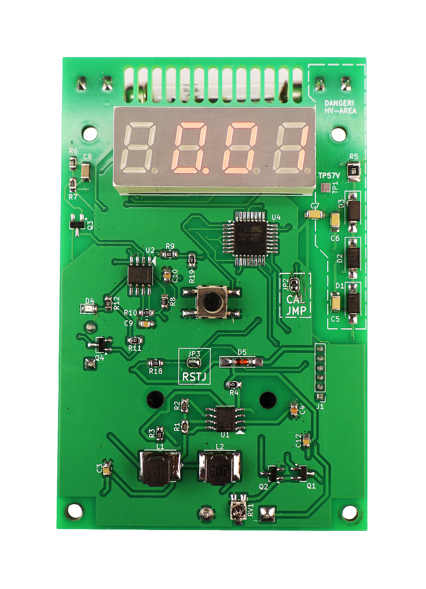
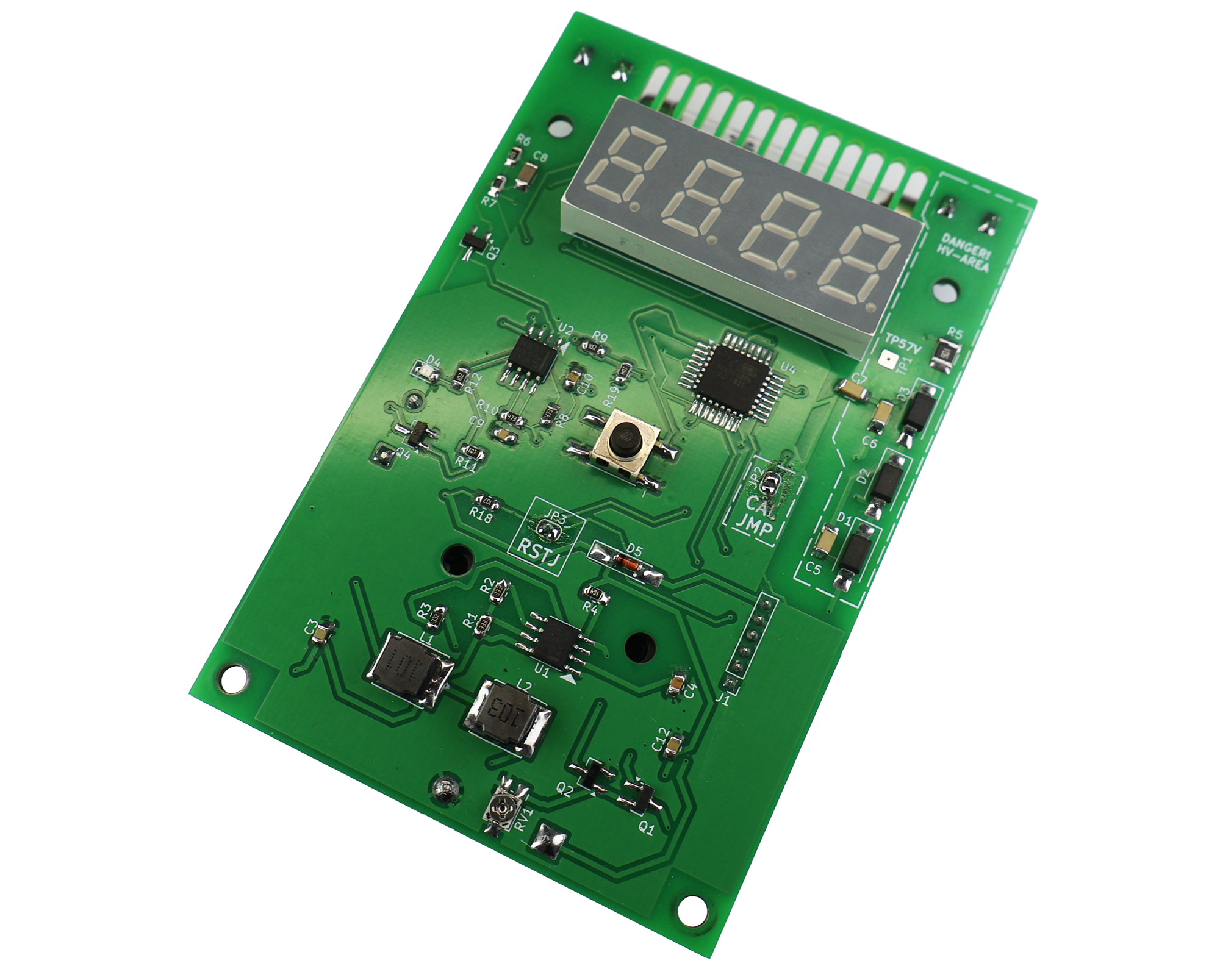
PCB Design Notes
The PCB is arranged so that the high-voltage circuitry is physically separated from the logic circuitry.
You can clearly see three zones:
- High-voltage generation
- Pulse processing
- Display and microcontroller
This layout reduces noise coupling and makes troubleshooting easier.
The front side contains:
- LED display
- Button
- Logic circuitry
The rear side contains:
- Battery holder
- Piezo buzzer
- Geiger tube
This arrangement keeps the design compact while remaining easy to assemble.